
What does solid-state mean? Solid-state, as the name expresses, refers to the use of a solid material to control electrons or the movement of electrons. To understand solid-state, it is necessary to know what came before it to understand why the term is used. Many electrical components that preceded solid-state devices used glass vacuum tubes or glass tubes filled with special gases to control electron flow. Yes, these were solid devices, but they had vacuum voids or special electron-transferring gases. The advent of the name solid-state occurred when the electron flow components became totally solid; that is, they had no glass, open areas or voids.
Solid-state components are current technology and some have been miniaturized compared to the first-generation solid-state components and the older vacuum tube technology. As a comparison, the first vacuum tube computers filled a large room and did not offer as many functions as today’s much smaller cell phones.
Here are the advantages of solid-state technology:
- Reduced equipment size
- Increased computing power
- Less heat and energy usage
- Durability
All of these advantages benefit the growth of electronic technology, which includes the control of heating ventilation air conditioning and refrigeration (HVACR) equipment.
Capacitors
Capacitors used on electric motors and compressors have a different function than capacitors used in solid-state circuits. Capacitors used on single-phase motors or compressors help start the motor rotation (start caps) or reduce running amps (run caps). The capacitors in solid-state circuits are used to create a smooth 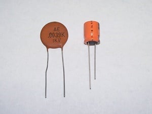 Figure 1direct current voltage from a rectified alternating sine wave. Capacitors in solid-state devices may also be designed to block or control current flow and direction. Figure 1 shows two different types of capacitors that might be seen in solid-state circuits. Capacitors used in solid-state circuits usually have a very low microfarad and voltage rating when compared to motor caps.
Capacitors are sometimes compared to batteries because they store electrons and because they both have two terminals. But capacitors are completely different from batteries. The battery creates a chemical reaction that develops electrons on one terminal and absorbs electrons on the other terminal. A capacitor, however, cannot create electrons; it merely stores them on its plates. Electrons do not travel through a capacitor. The capacitor terminals are connected to two plates separated by an electrically insulating material. The insulating material is called a dielectric. One way to think of a capacitor is to imagine two pieces of aluminum separated by a piece of insulating paper. Electrons are stored on the capacitor plates.
Diodes
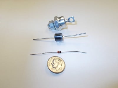 Figure 2A diode, as shown in Figures 2 and 3, is a two-a terminal electronic component that conducts electric current in only one direction. Think of it as an electron check valve. The term usually refers to a semiconductor diode, the most common type today. A semiconductor is a crystalline piece of semiconductor material connected to two electrical terminals.
The most common function of a diode is to allow an 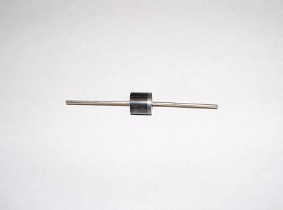 Figure 3electric current to pass in one direction while blocking current in the opposite direction. Thus, the diode can be thought of as an electronic version of a check valve. This unidirectional behavior is called rectification or changing. This is used to convert alternating current to direct current.
Transistors
The transistor is compared to its predecessor, the glass vacuum tube. A transistor, as shown in Figure 4, is a semiconductor device used to increase or amplify an electrical signal. It can also be used as an electronic switch. It is made of a solid piece of semiconductor material that normally has three terminal connections, as labeled in Figure 5. Some transistors are used individually, but most are miniaturized and embedded in an integrated circuit (IC).
The transistor is the fundamental building block of modern electronic devices. The transistor was first used in its simplest form in the early 1950s. Its 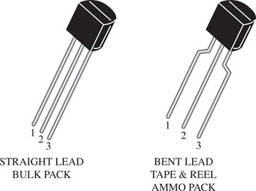 Figure 4lower power requirements and compact size allow for a reduction in equipment size. The earliest example of commercial transistor use is the small portable radio, now known as the larger “boom box.” The first computers had few solid-state components and were as big as a room and had less calculating power than today’s average laptop and other portable devices. The advent of the transistor
 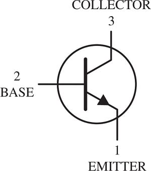 Figure 5and other solid-state devices allowed the computer size to shrink, and the power requirements to drop significantly. This paved the way for personal computers (PC), then laptops, and other every-day computing devices.
The small size and weight advantages of the transistor helped start the rush to miniaturize electronic devices. Other advantages of transistors are that they do not require a warm-up period, and they use less power; therefore, they have less heat to dissipate. The lower power requirement translates into higher efficiency operation. Transistors have a long life, are highly reliable and are physically rugged.
Integrated circuits
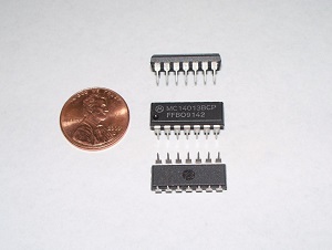 Figure 6: These three ICs are miniaturized circuits designed to fit into one shell or case.An integrated circuit or IC contains many transistors and other solid-state devices installed in one component and mounted on a circuit board. Sometimes called a chip, the IC is connected to the circuit board by metal pins, as shown in Figure 6. The IC is truly miniaturization of most of the components discussed in this article. The IC is used in virtually all electronic equipment found in circuit boards.
Rectifiers
A rectifier is an electrical device that converts alternating current (AC) to direct current (DC). Many solid-state devices use DC power. The rectifier blocks part of the AC wave to modify it so that it is closer to a DC voltage. For example, the rectifier can be designed to chop off the bottom half of an AC voltage sine wave. The rectifier by itself does not create a straight-line DC voltage. It may need additional 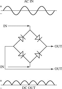 Figure 7: The upper part of the diagram represents a standard AC sine wave; the middle section illustrates a bridge rectifier diagram; the lower diagram shows the AC that has been modified by the bridge rectifier.rectifiers, diodes and capacitors if a straight-line DC voltage is required.
Figure 7 shows four rectifiers wired into a bridge rectifier circuit. The bridge rectifier is also called a full-wave rectifier. The upper part of the diagram shows a normal AC sine wave, 60 hertz per second. The middle diagram shows how the four rectifiers are wired to create the bridge rectifier circuit. The lower diagram is the modified output voltage. The modified DC is not a flat-line voltage as expected from a battery voltage, but a choppy positive voltage that may be adequate for some DC circuits. The choppy DC voltage can be cleaned up with capacitors and other solid-state components if required by the DC operation.
Figure 8 shows two different types of bridge rectifiers. The identifying feature of a bridge rectifier is the four-wire connections. The size of the rectifier will 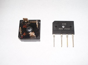 Figure 8determine its current-carrying capabilities.
Rectification may occasionally serve in roles other than to generate DC voltage. For example, in gas heating systems, pilot flame rectification is used to detect the presence of a small flame that will be used to light the burners. Two metal electrodes placed in the pilot flame provide a current path through the flame. The flame is actually a conductor that modifies the AC voltage. The rectification of an applied AC voltage will happen in the pilot flame plasma, but only while the flame is present to generate it. The partial DC voltage is used to signal a safety control that the pilot flame is present, and the gas valve can open for burner ignition. This starts the ignition process.
Varistors
A varistor is a two-element semiconductor with reverse resistance in which the resistance drops as the applied voltage increases. They are also called metal oxide varistors (MOVs). The symbols for a varistor are shown in Figure 9. An MOV is illustrated in Figure 10. At first glance, note that the MOV has the same appearance as a capacitor used in solid-state circuits. But the MOV has a raised line that is not commonly 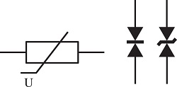 Figure 9found on capacitors. Think of the MOV as a lightning rod for high voltages, directing dangerous voltage away from the component it is protecting.
Varistors are often used as a safety device to short circuit transient high voltage in electron circuits. A transient voltage is a high-voltage spike that can last long enough to cause component damage. This can occur, for example, when applying a short-term, transient 200 V to a 120 V circuit. The longer the higher voltage is applied, the more likely it is that the components will be damaged. 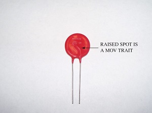 Figure 10Even a short-term high-voltage spike can open a motor or coil winding or damage sensitive solid-state devices. The MOVs are wired in a circuit so that when they are triggered at a higher than normal voltage, they will direct the current created by the high voltage away from the component they are protecting. A varistor is also known as a voltage-dependent resistor (VDR).
The common varistor is the MOV, which is used to build a typical surge protector power strip. The MOV is a ceramic mass of zinc oxide grains sandwiched between two metal plates. The result of this design is a highly nonlinear current-voltage characteristic in which the MOV has a high resistance at low voltages and a low resistance at high voltages. The MOV works well in shorting line voltage transients from the component it is protecting.
What MOVs do not do
An MOV will not control a surge of lighting. Lighting is generally at a higher magnitude than a voltage spike and will destroy the MOV and possibly the equipment it is trying to protect. The use of a series-connected thermal fuse is one way to protect against a catastrophic MOV failure.
A varistor provides no equipment protection against:
- Inrush current surges
- Overcurrent created by a short circuit
- Voltage sags (also known as brownouts); it neither senses nor affects such events
Microcontrollers and microprocessors
The microcontroller is basically a dedicated computer that operates one major component. A microprocessor, also known as a central processing unit or CPU, is designed to operate complex systems. The CPU can be designed to perform multiple functions in an HVACR system. The electronic expansion valve (EXV) can be controlled by a simple CPU or microcontroller. The electronic control attached to the EXV measures various refrigerant line temperatures, motor temperatures and converted pressures to control an accurate EXV superheat. Accuracy is within ±1° F of the set superheat temperature.
Circuit boards
Solid-state components are mounted on circuit boards, sometimes called printed circuits. The top and bottom 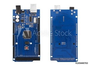 Figure 11. Source: Adobeof a circuit board are shown in Figure 11. The components are placed in the top part of a circuit board, and the installations are identified by letters on the board. For example:
- R = resistor
- I = integrated circuit
- D = diode
- K = relay
- P = plug-in connection
The bottom side of the board, as shown in the figure, shows the component connection lines and solder points. The connection lines replace the use of wires. They are usually copper strips but can be silver or gold in special applications.
Summary
This article was designed to give a brief overview of electronics without overwhelming readers with electron theory. It briefly discussed the operation of diodes, transistors, rectifiers, varistors and circuit boards. Electron theory is important when working directly with electronic circuit boards. In this industry, however, circuit boards are good or bad. It is not necessary to know which component is defective. It is rare to attempt any field repairs on circuit boards, other than changing a blown fuse.
