Sponsored Content
Analog/Mixed Signal
Panasonic polymer capacitors vs. MLCCS
28 February 2019
Sponsored content
Capacitor technology selection often seems like a simple choice, but the demands, challenges and expectations of modern electronics prove otherwise. The need continues to grow for capacitor technologies that deliver high reliability, long life, stable performance, low equivalent series resistance (ESR) and low cost.
Polymer capacitors have met these needs in the enterprise, commercial, consumer, medical, and aerospace segments for more than 15 years. However, they have yet to conform to AEC Q200 requirements, which relate to stress in automotive use. These challenges are being addressed as polymer capacitors enter into the automotive segment.
To exemplify the issue of capacitor performance, consider DC-DC converters and how their requirements have changed. Because ICs have been developing in the direction of higher speed, larger current and lower voltage, converters must meet these characteristics. Converters therefore require faster transient response to support the ICs. Both input and output capacitors are required for a DC-DC converter to function properly. Output capacitors in DC-DC converters store the energy and smooth the voltage while input capacitors are for power dissipation and ripple.
Various capacitor technologies are available for the input and output of DC-DC converters. Table 1 ranks the performance characteristics of various kinds of capacitors, including electrolytic capacitors, conductive polymer aluminum solid capacitors (OSCONs), polymer aluminum capacitors (SP-Caps), tantalum solid polymer capacitors (POS-Caps), film capacitors and multilayer ceramic capacitors (MLCCs). Application typically dictates the best choice of capacitor.
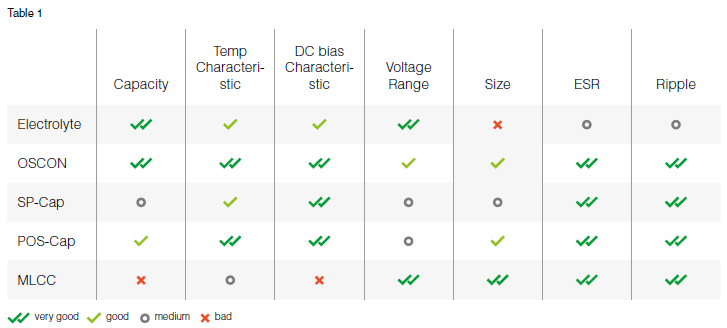 Table 1. A table comparing capacitor technologies. Source: Panasonic
Electrolytic capacitors provide the largest ESR but suffer significant degradation in capacitance and leakage current at higher temperatures and frequencies. Ceramic capacitors have a low ESR and equivalent series inductance (ESL) and are great for transient performance but have limitations on capacitance derating. Ceramic capacitors can operate at high ripple currents but they suffer non-graceful aging failure and require low operating electric fields. Polymer electrolytic capacitors are mainly used in power supplies of integrated electronic circuits as buffer, bypass and decoupling capacitors. They are often used in devices with flat or compact design. Thus, they compete with MLCCs but offer higher capacitance values than MLCCs and display no microphonic effect, such as class 2 and 3 ceramic capacitors.
MLCCs are by far the most widely used capacitor type in DC-DC converters. Polymer capacitors, as well as conventional aluminum electrolytic capacitors, have large capacitance and excellent bias characteristics, with which MLCCs can never compete.
Polymer capacitors have high reliability and superior low-temperature characteristics by using solid polymer materials as an electrolyte. SP-Caps and POS-Caps, with their small size factor and cubical form, are good replacements for MLCCs.
Capacitor selection criteria
Stable vs. frequency
Polymer capacitors exhibit very similar performance to multi-layer ceramic capacitors (Figure 1).
Capacitance density and stability vs. DC bias
MLCCs cannot achieve the same high capacitance as polymer capacitors for the same given footprint and volume. An MLCC exhibits strong capacitance dependence on DC bias due to the ferroelectric dielectric materials used for MLCCs.
The capacitance of MLCCs varies with applied DC voltage, which can lead to a capacity drop of more than 70% compared to the given specs on the data sheet. For polymer capacitors, the capacitance does not vary significantly when the application voltage changes (Figure 2).
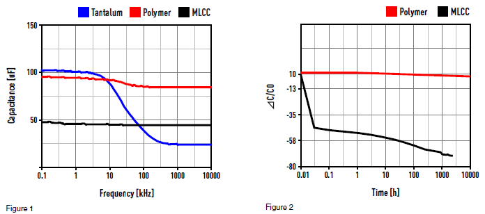 Figures 1 and 2: Capacitance stability with frequency and voltage. Source: Panasonic
Stability vs. temperature
In polymer capacitors, the capacitance grows in parallel to the temperature rise. The temperature characteristics of MLCCs differ according to the dielectric type, but all of them suffer aging failure by exhibiting temperature dependency (Figure 3). Ceramic capacitors also are brittle and sensitive to thermal shock, so precautions to avoid cracking during mounting need to be taken.
Piezoelectric effects in ceramic chip capacitor
Piezoelectric effects in capacitors can cause unexpected signals in certain circuits. MLCCs cause a physical deformation at a frequency range from 20 Hz to 20 kHz, and could be audible to humans. This vibration can also cause flex cracking due to excessive circuit board flexure (Figure 4).
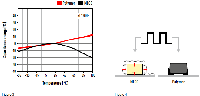 Figures 3 and 4: Capacitance changes with temperature. Piezoelectric effect of MLCCs. Source: Panasonic
Robust
Cracks in ceramic surface mount technology components limit assembly reliability and yields. MLCCs are exposed to different reliability tests, including thermal shock, board flex (bending) and biased humidity tests, depending on the targeted applications. Layout guidelines recommend MLCCs are not placed at the edges of the board, among other restrictions (Figure 5).
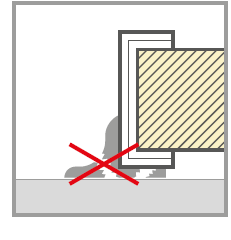 Figure 5: Stress cracking. Source: Panasonic
Safety
If the capacitor experiences a voltage between its terminals higher than its rated voltage, the dielectric may break down and create a short. Most ceramic capacitors are built with a safety margin and do not experience catastrophic failure. Wet electrolytic capacitors can overheat causing the electrolyte to evaporate. Solid polymer capacitors do not have such risks — the capacitor either shorts or starts acting like an open circuit toward the end of its lifetime. Generally speaking, the reliability of polymer capacitors is much better than the reliability of electrolytic capacitors and particularly MLCCs.
Conclusion
The comparison of the characteristics outlined above is only partial in nature. Each type of capacitor is well suited to some fields and poorly suited to others. When actually designing circuits, it is necessary to consider a number of factors in addition to the characteristics.
Taking these considerations into account, capacitors in the 2 V to 100 V range and 2.2 µF to 2,700 µF range are good candidates for MLCC replacements with polymer capacitors. Often this change will provide better reliability and take up less space on the circuit board.
Get your Panasonic Polymers from TTI.
Powered by CR4, the Engineering Community
Discussion – 0 comments
By posting a comment you confirm that you have read and accept our Posting Rules and Terms of Use.
Advertisement
Advertisement
Popular News
Find Free Electronics Datasheets

Advertisement