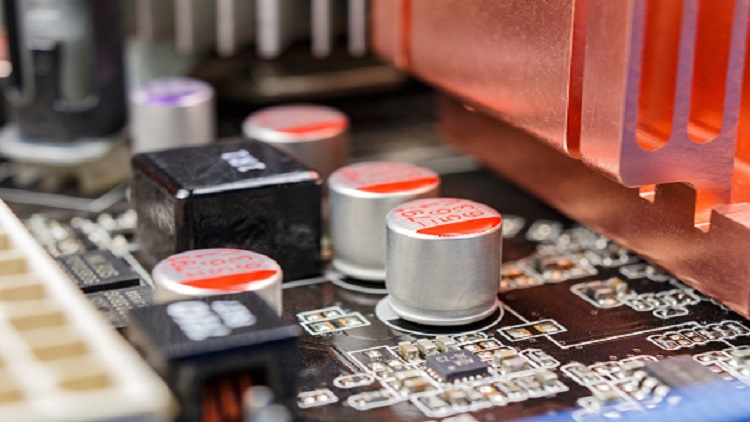
Capacitors are among the essential passive components that play an essential role in electric circuits. They help store electrical energy in the form of an electric field between two plates.
However, while seemingly simple, there are many factors and considerations that go into the proper selection and application of capacitors in an electric circuit. For instance, engineers need to understand the different methods of connecting capacitors and how each method suits different application requirements.
This article will get back to the basics of capacitors and capacitor circuits. It will explain how capacitors work, the different types of capacitor circuits, and their suitability for different application requirements.
How does a capacitor work?
To understand how capacitors work, consider a simple household water distribution system that features a tank and water pump connected to a pipe network. This system is usually designed such that the tank stores water when the water pump operates. This storage allows end-users to get a steady supply of water even when the pump stops working.
Capacitors in electric circuits act as the water tank in the previous analogy. However, instead of storing water, a capacitor stores electrons and releases them when they are needed. A typical capacitor is made of two conducting metallic plates separated by a vacuum (or dielectric).
Consider a simple electric circuit that features a capacitor connected to a battery, as shown in Figure 2. The capacitor plate connected to the battery's negative terminal accepts electrons from the battery and becomes negatively charged. In contrast, the plate connected to the battery's positive terminal loses electrons to the battery and becomes positively charged. The dielectric material ensures that no electron passes through the plates, causing the capacitor to store electrons.
![Figure 2: Capacitor connected to a battery. Source: Rameek85/CC [SA][4.0]](/images/assets/743/18743/capacitor_figure_two.jpg) Figure 2: Capacitor connected to a battery. Source: Rameek85/CC [SA][4.0]
Figure 2: Capacitor connected to a battery. Source: Rameek85/CC [SA][4.0]
The storage potential of a capacitor is called capacitance. It varies with the overlapping surface of the conducting plates, according to the equation below:
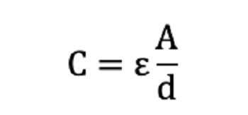 Equation 1: Capacitor capacitance equation.
Where:
C = Capacitance of capacitor (F)
E = Absolute permittivity of the dielectric material (F/m)
A = Plate area i.e., surface area of the metallic plate overlap (m2)
d = Plate spacing i.e., distance between the plates (m)
This equation shows that capacitance increases with the surface area of the conducting plates and decreases with the distance between the metallic plates. In addition, the capacitance of a capacitor depends on the choice of the dielectric material used.
[Learn more about how capacitors work with Engineering360]
Capacitor connections: Series and parallel circuits
The two common types of capacitor connections are series and parallel circuit connections. Depending on the type of connection, engineers can vary the equivalent voltage and capacitance of the circuit.
Capacitors in series
Figure 3 shows a typical series connection of capacitors.
![Figure 3: Capacitor placed in series connection. Source: Omegatron/CC [SA][3.0]](/images/assets/743/18743/capacitors_fig_three.jpg) Figure 3: Capacitor placed in series connection. Source: Omegatron/CC [SA][3.0]
Figure 3: Capacitor placed in series connection. Source: Omegatron/CC [SA][3.0]
Assuming the capacitors are connected to a battery with a voltage VT, the total voltage across these capacitors can be calculated using:
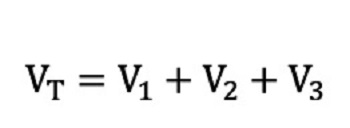 Equation 2: Series capacitors total voltage.
Likewise, the equivalent capacitance of this circuit can be calculated using:
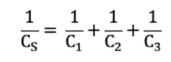 Equation 3. Equivalent capacitance of series capacitors.
Where:
Cs = equivalent capacitance of the capacitors in series
Therefore, for n number of capacitors placed in series connection, the equivalent capacitance is given by:
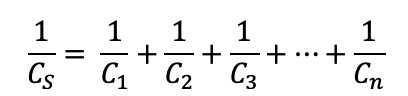 Equation 4. Equivalent capacitance for capacitors in series.
The equation shows that when two or more capacitors are connected in series, the equivalent capacitance is always less than the capacitance of any of the capacitors in the connection. However, the voltage across the whole capacitor connection is the sum of the voltage across individual capacitors.
Series connection of capacitors is desirable in applications where high working voltage is required. For instance, consider a scenario where a 3 kV power supply needs to be filtered using capacitors. If the available capacitors have a rating of 1 kV, then engineers can connect three (or more) of these capacitors in series to allow the 3 kV voltage to be divided across the capacitors.
Capacitors in parallel
Figure 4 shows a typical parallel connection of capacitors.
![Figure 4: Capacitors in parallel connection. Source: Omegatron/CC [SA][3.0]](/images/assets/743/18743/capacitors_fig_four.jpg) Figure 4: Capacitors in parallel connection. Source: Omegatron/CC [SA][3.0]
Figure 4: Capacitors in parallel connection. Source: Omegatron/CC [SA][3.0]
Unlike in series connection of capacitors, the total voltage across capacitors placed in parallel connection is the same, as shown in the equation below:
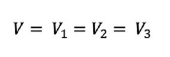 Equation 5: Voltage of capacitors in parallel.
The equivalent capacitance of this circuit can then be calculated using:
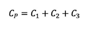 Equation 6. Equivalent capacitance of capacitors in parallel.
Therefore, for n numbers of capacitors placed in parallel connection, the equivalent capacitance is given by:
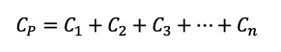 Equation 7. Capacitors in parallel connection, quivalent capacitance.
The equation shows that when capacitors are connected in parallel, the equivalent capacitance of this connection is greater than the capacitance of any capacitor in the connection. Parallel connection of capacitors is ideal in applications where there is a demand for more energy storage capability.
Voltage rating of capacitors
The voltage rating of a capacitor is the maximum voltage that the capacitor is designed to withstand during operation. Subjecting a capacitor to a higher supply voltage than its recommended voltage rating causes arching between the plates of the capacitor, which causes a short circuit and damages the dielectric material and capacitor.
For safety reasons, it is recommended that engineers choose a capacitor with a voltage rating that is at least 50% of the supply voltage.
While this article presents the basics of capacitors and capacitor circuits, there are still several things an engineer must understand when specifying capacitors for a particular application. For instance, engineers need to know about the types of capacitors and polarity, among other things. Engineers are advised to reach out to capacitor suppliers to discuss their application requirements.
