
Resistors are essential passive components used in pretty much every electronic circuit to resist the flow of electric current. However, the level by which resistors resist electric current primarily depends on the resistors' resistance rating (or value).
There are different approaches to determine the resistance values of resistors. One such method involves interpreting color bands on the resistors, and another involves using a digital multimeter.
This article presents helpful information about determining the resistance values of resistors. It will guide technicians looking to understand resistor color code schemes and how to measure resistance using digital multimeters.
Resistor color coding
Resistor color coding is used to provide information about small leaded resistors. It is defined in the international standard IEC 60062, which provides marking codes for resistors and allows technicians to determine the resistor's resistance, tolerance value and sometimes reliability.
Resistor color codes are given by several color bands that vary from three to six, with each type of color band having its unique representation. Figure 1 presents a chart that allows technicians to determine resistors' resistance and tolerance values with color bands. To use this chart, the technician only has to identify the resistor color bands, understand what these bands represent and determine their values from the chart.
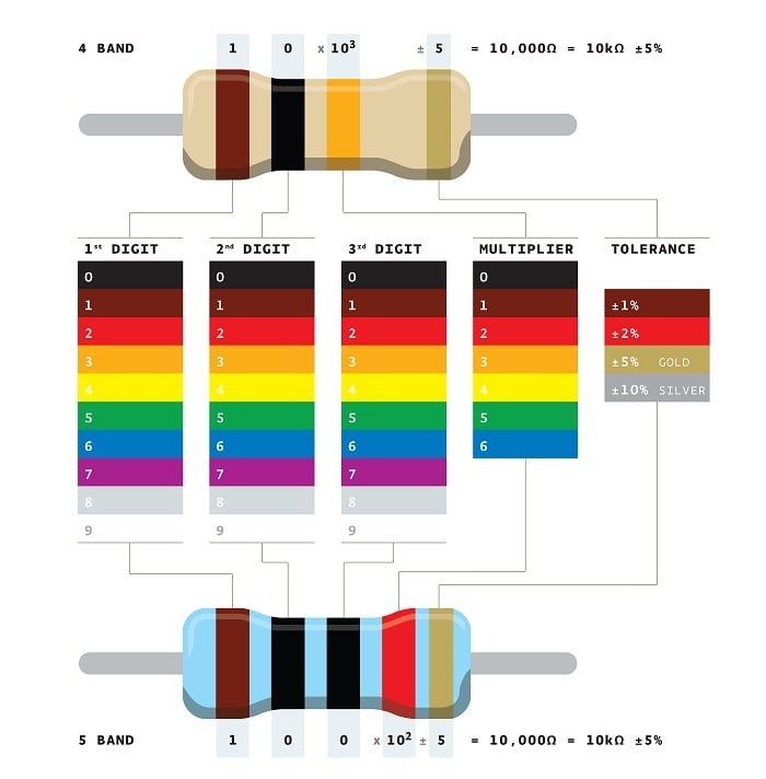 Figure 1: Resistor color coding. Source: Adim Kassn/CC SA 3.0
Three or four-band resistors
In a three-band resistor, the first two bands represent the first two digits of the resistance value, while the third band represents the multiplier. In a four-band resistor, the first three color bands have the same interpretation as the three-band resistors. However, the fourth band denotes the tolerance value of the resistor.
So, for example, consider the four-band resistor in Figure 2.
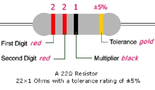 Figure 2: Four-color band resistor. Source: Direct/CC SA 3.0
The first two colors of the band are red, so the first and second digits of the resistor are “2” and “2.” The third color of the band is black, so the multiplier is obtained to be 1. Finally, the fourth color of the band is gold, so the tolerance of the resistor is obtained to be ±5%.

Five or six band resistors
In five or six color band resistors, the first three bands represent the first three digits of the resistance value, while the fourth and fifth bands denote the multiplier and tolerance values, respectively. The sixth color in a six band resistor denotes the resistor’s temperature coefficient. This value gives the technician an idea about the reliability of the resistor.
However, keep the following points in mind when reading resistance values using color codes:
- In color-coding, resistors typically have the color band grouped together toward one end. The resistance color code reading starts from the side of the grouped band.
- A resistor with a single black band is a zero-ohm. It is basically a wire link to connect wire traces on a PCB (printed circuit board).
[Learn more about resistor color coding and power rating on Globalspec.com]
How to measure resistance using a multimeter
More often than not, technicians find resistors with faded colors, making it challenging to determine the resistance value using the color-coding approach. In such a scenario, a multimeter can be used to measure the resistance value of the resistor.
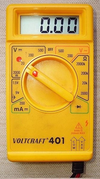 Figure 3: A digital multimeter. Source: Cjp24/CC SA 3.0To measure the resistance of a resistor using a multimeter, technicians should follow the steps below:
1. Set the multimeter such that the black probe is inserted into the COM (common) port, and the red probe is inserted into the port having the visible voltage (V) or Ohm sign (Ω).
2. Turn on the multimeter.
3. Set the multimeter dial so that the arrow points to the ohm (Ω) symbol. Digital multimeters typically have a measuring range of 6 Ω to 6k Ω (in 6, 60, 600, 6,000 Ω step). Technicians should select the range so that the expected resistance value is less than but close to the maximum of the range
4. Place the multimeter probes on the terminals of the resistor and read the measured value from the display screen of the multimeter.
Engineers and technicians are advised to take the following precaution while using the multimeter to measure resistance.
- Remove the resistor from the circuit connection or power off the circuit before taking measurements. Also, discharge all capacitors in the circuit before taking resistance measurements.
- Avoid touching the terminals of the resistor as it might alter the resistance of the resistor.
Conclusion
While this article presents helpful information to determine the resistance values of resistors, technicians are advised to reach out to resistor suppliers for the necessary manuals and documentation on their resistors.
