
Radio frequency (RF) interference can occur anytime that multiple transmitting and receiving RF systems are operating near each other. Such interference can occur when multiple antennas are mounted on an aircraft, automobiles, ships and many other platforms
A major challenge in RF interference analysis is obtaining high fidelity, broadband characterizations of the transmitting and receiving RF systems. Measured data, especially broadband data, are not readily available for most RF systems. Vendors are required to demonstrate that their equipment meets the various military and commercial standards for transmitter emissions and receiver susceptibility, however, the raw measured data is generally not made available to the analyst. Even when such data can be obtained, it often lacks the fidelity necessary for RF interference analyses.
RF interference analysis requires a model of the transmitter (Tx) emissions that encompasses a wide frequency range. Transmitter harmonics are typically the strongest out-of-band emissions and occur at integer multiples of the transmitter carrier frequency. Harmonic amplitude generally decreases with increasing harmonic order, and it is common practice in RF interference analysis to model up to the 10th harmonic.
Transmitters also generate spurious emissions that can occur at any frequency but are typically found relatively close to the fundamental frequency due to filtering internal to the transmitter. A Tx measurement with sufficient bandwidth to capture the fundamental and up to the 10th harmonics can be achieved with many modern spectrum analyzers, but there are limitations related to the frequency resolution.
An Automated Radio Measurement System (ARMS) is under development by EMA Inc. and National Instruments to provide the high fidelity measured data required to accurately assess real interference problems during the design phase. The utilty of ARMS as an automatic measurement system for out-of-band RF system characterization is highlighted in the diagram (orange) with an example of measured transmitter data collected for the ICOM ID-51A tuned to 146 MHz. A simple model for the transmitter based upon information found on the specification sheet for the radio is overlaid with the black trace to underscore glaring differences between parametric models and measured data.
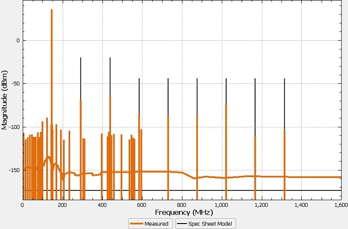 Source: EMA Inc.
Numerous spurious emissions occur both below and above the fundamental frequency, but the spec sheet-based parametric model has no knowledge of the spurious emission frequencies. Most of the measured harmonics are observed to be 30 dB or more lower than the harmonic amplitudes based upon the specification sheet information.
Real interference issues are detected early in the design phase with fast, accurate measurements generated by ARMS.
