Buck converters are a fundamental building block in modern electronics for efficient and precise voltage regulation in a wide range of applications. They take a higher voltage and turn it into a lower voltage with more current. Many electronics necessitate specific voltages in order to function. Unlike linear regulators (another voltage converter option) that waste extra voltage as heat, buck converters are much more efficient (over 90% sometimes). This means buck converters don't need a lot of cooling as less energy is wasted as heat, and in portable electronics, buck converters help extend battery life by using power more efficiently.
How does a buck converter work?
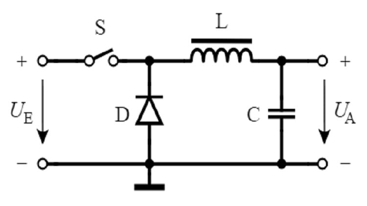
A buck converter has a switch, an inductor, a diode, a capacitor and a load. A switch, usually a metal-oxide semiconductor field-effect transistor (MOSFET), acts as a quick on/off trigger, controlling the flow of electricity. The inductor coil resists current changes by storing energy when the current is flowing and releasing it when the current stops. The diode is a one-way valve that allows electricity to flow in one direction only, and the capacitor acts like a tiny battery, storing electrical energy to smooth out the output voltage.
The complete workings of a buck converter can be understood by observing its behavior in the “switch on” and “switch off” states. During switch-on, the transistor turns on, connecting the input voltage to the inductor. Current starts flowing through the circuit, and the inductor builds up its energy, resisting the current increase. This rising current also charges the capacitor. During switch-off, the transistor switches off, disconnecting the input voltage. Since inductors resist changes in current, the current keeps flowing through the diode (which allows current in this direction) and charges the capacitor further, powering the load.
In most practical buck converters, a control circuit monitors the output voltage. If it's too low, the switch will stay on for a longer duration (duty cycle) in each cycle to deliver more power. If the output voltage is too high, the switch will be on for a shorter duration, reducing power delivery. By adjusting the on/off time (duty cycle) of the switch, the amount of energy transferred from the input to the output is controlled to effectively step down the voltage. The inductor and capacitor work together to smooth out the output voltage, providing a steady flow of power to the device.
What is the role of the duty cycle?
In a buck converter, a duty cycle refers to the ratio of the time the switch is ON compared to the total switching period. It's a critical factor in determining the output voltage of the buck converter. Let’s consider the switch in the buck converter circuit as a light switch. When it's ON, the input voltage is directly connected to the inductor, allowing current to flow. When it's OFF, the connection is broken. The duty cycle is expressed as a percentage. A 50% duty cycle means the switch is ON for half of the switching period and OFF for the other half. A 25% duty cycle means the switch is ON for a quarter of the period and OFF for the remaining three-quarters.
By adjusting the duty cycle, we control how much time the input voltage has to flow through the inductor and ultimately to the output. If the switch is ON for a longer duration (higher duty cycle), the input voltage has more time to transfer energy to the inductor and ultimately the output. This results in a higher output voltage (closer to the input voltage). Conversely, if the switch is ON for a shorter period (lower duty cycle), the input voltage has less time to influence the output. This leads to a lower output voltage. Essentially, the duty cycle acts like a volume knob for the output voltage. By adjusting it, users can regulate how much of the input voltage gets transferred to the output, achieving the desired step-down voltage.
[Find manufacturers and suppliers of buck converters on GlobalSpec]
Applications of a buck converter
· Laptop: Once the AC wall outlet voltage is converted to DC by the charger, the DC voltage enters the laptop. Inside the laptop, a buck converter takes this DC voltage (around 19 V DC) and steps it down further to the various lower voltage levels required by different components like the CPU, memory and graphics card (usually ranging from 1.8 V to 12 V DC).
· Cars: Modern cars have several electronic systems that operate at different voltage levels. Buck converters, often integrated into DC-DC converters, are used to regulate the voltage supplied to these systems from the car's main battery (which is typically 12 V). This ensures each system receives the appropriate voltage for optimal performance.
· LED lights: LED lights often need a lower voltage than the power source. Buck converters are used in LED drivers to provide the correct voltage for the LEDs to function properly. This allows LEDs to operate efficiently and consume less power.
· Battery chargers: Many battery chargers, especially for lithium-ion batteries used in portable electronics, incorporate buck converters. These converters regulate the voltage going to the battery during the charging process. This ensures the battery receives the correct voltage to charge safely and efficiently, preventing damage from overcharging.
[See also: Operating and design principles of boost converters]
Conclusion
Buck converters convert a higher voltage to a lower voltage while increasing the current. By modifying the duty cycle, the amount of time the input voltage can pass through the inductor and reach the output is regulated. A longer duration of the switch being on (a greater duty cycle) leads to an increased output voltage, which approaches the input voltage. If the switch is on for a shorter period (lower duty cycle), the output voltage becomes less than the input voltage.
