Sponsored Content
Critical Communications
Key MMIC LNA Choices That Can Make or Break a Receiver Design
30 August 2018

Sponsored content
Low-noise amplifier (LNA) MMICs are a critical component in virtually all radar, wireless communication and instrumentation systems. There are a wide range of options and tradeoffs an engineer must consider when picking an LNA MMIC for a particular system design. The noise figure is often the feature of primary focus, as noise figure defines the sensitivity of the receiver, a critical system requirement. After noise figure, other project specific needs related to performance, size, weight, power and cost (SWaP-C) are then considered. Often these features are not heavily weighted, but they can make a big difference in advanced microwave applications.
Keeping these additional parameters in mind may help an engineer save time during the design cycle, save money during assembly and enhance a product’s competitive advantage, leading to valuable contract wins.
Pinpointing the LNA in the Microwave Signal Chain
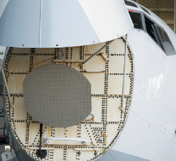 Phased array and AESA radar systems are being retrofitted into both commercial and military aircraft. They employ dozens of LNA MMICs that are relied on for receiver sensitivity and optimal signal-to-noise ratio (SNR).
Receiver sensitivity and signal-to-noise (SNR) are two of the most critical electrical performance considerations for modern wireless communications, radars, instrumentation and satellite communications.
Largely, the noise performance of the receiver is defined by the performance of the LNAs used in these circuits.
Advanced applications, such as electronically steered arrays (AESAs) for military applications and phased array antennas for 5G wireless communication systems, require massive numbers of transmit/receive (T/R) modules, with each receive channel requiring an LNA.
1. Input Power Survivability
Specifically in military and aerospace radar and communications applications, where electronic countermeasures (ECMs) may be used to overwhelm a receiver, a receiver must be capable of withstanding high levels of input power for varying intervals of time. Active or passive jamming can cause levels of noise and frequency bursts that couple large amounts of microwave energy into a receiver. Moreover, in many systems a high-power transmitter is in close proximity to the receiver, which can also lead to substantial power into the receiver front end.
Many of the latest applications, such as wideband and multi-band communications transceivers, and low probability of intercept/low probability of detection (LPI/LPD) radar (often employing frequency hopping) use extremely wide bandwidths of spectrum for transmission and reception. These factors lead to greater noise power coupled into the receiver, and less protection from the aggressive filtering possible in narrowband receivers. If the amount of noise or interference exceeds certain limits, a receiver may be overloaded and unable to function as designed.
If the receiver is exposed to these power levels for too long, the components within a receiver may suffer accelerated aging, performance degradation or outright destructive failure.
A common method to reduce the impact of critically high input powers to a receiver is to include a limiter or circulator on the input of a receiver chain. An unfortunate side effect of adding anything prior to the LNA in the receiver is the degradation of the overall system noise figure.
This circuit will reduce the sensitivity of the receiver, which may shorten communications range, through- put, radar range and accuracy, and cause delays in acquiring mission critical information. For example, a superior system noise figure of 1 dB can rise to 2 dB or more when a limiter is added.
Therefore, it is very important to consider an LNA’s highest input power handling (or input survivability) when choosing a component. Most LNAs can handle only 10 dBm pulsed on their input, but some can now survive 20 dBm continuously and 23 to 25 dBm pulsed. Such protection levels can in many cases eliminate the limiter.
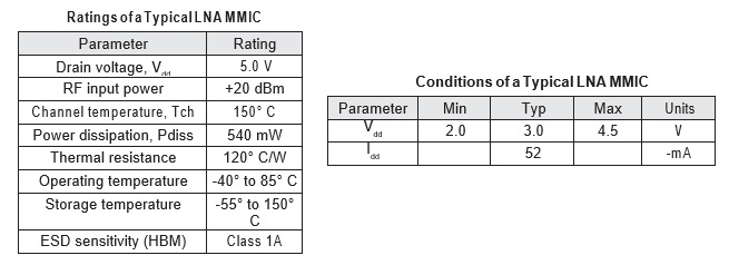 Understanding and carefully operating LNA MMICs to their specified maximum power ratings and operating conditions is critical to ensuring reliability and long life.
2. Gain Flatness and Gain Stability Over Temperature
Gain flatness with frequency is essential for wideband communications systems to achieve the required inter-symbol-interference (ISI) levels of complex digital modulations schemes. Similarly, gain flatness can affect the range performance of radar systems. Equalizers are often employed to compensate for the gain slope of typical LNAs. It is important to note many LNA suppliers use different bandwidths to characterize gain flatness, often without indicating what the gain flatness is across the entire band.
Another factor to consider about LNA performance, which is often omitted from datasheets, is the gain stability over temperature (Figure 1). In applications such as aerospace communications and satcom, the operating temperature variations can exceed 180° F within a short time window.
Temperature changes that are significant can affect an LNA by more than just changing the noise figure of the device and system; they can vary the frequency dependent gain of the LNA. For example, large phased array antennas may have thousands of T/R modules, with many of the modules exposed to a variety of temperature gradients. If the communications system relies on gain stability throughout the TR modules, and the LNA’s gain variation over temperature is too large, the system may suffer a loss in performance that impacts the bottom line of the deployment.
Recognizing this, system designers should opt for LNA designs that exhibit both superior gain flatness and gain stability over temperature.
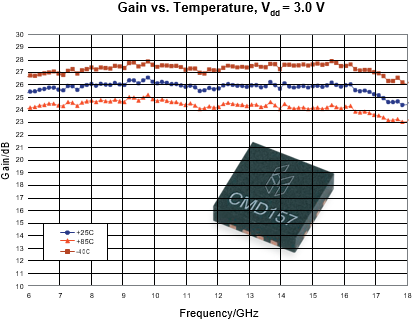 This 6-18 GHz LNA exemplifies how gain flatness and gain stability over temperature are possible in a single device.
3. Supply Voltage
Properly biasing a MMIC amplifier is critical to achieving adequate device performance. Depending upon the particular LNA design, the biasing circuitry could be composed of a positive and negative biasing circuit with temperature compensation. With such a dual bias scheme, the positive and negative voltage supply must be provided in the correct sequence, or else device failure can result.
When designing at a system level for a large RF or microwave assembly, many different voltage supplies may be required. Certain design constraints may also limit the noise and stability performance of those power supplies, which may impact the practical LNA performance due to limited power supply rejection ratio (PSRR). To avoid this, additional circuitry may be used to condition the voltage supplies for a given LNA MMIC. Each of these circuits and connection points introduces a potential failure mode to the voltage supplies, and thus impacts system reliability. These supply-voltage circuits also consume valuable assembly real estate and power, contribute to the overall size or weight of the assembly, add costs and of course, consume design and test time.
In order to reduce the infrastructure necessary to integrate a MMIC LNA into a microwave assembly, Custom MMIC has applied innovative circuit-design techniques. The approach has resulted in MMICs which only require a single positive voltage supply, enabling a wide range of voltage input options for greater flexibility. All of the necessary circuitry to properly bias these LNAs is integrated into the MMIC itself. Ultimately, when the MMIC requires only a single positive supply voltage it reduces the bill of materials, overall system complexity, failure modes and overall system SWaP-C.
4. Power Consumption
For many ground-based and stationary RF communications and radar systems, the power consumption of an LNA is not a significant consideration. However, the latest AESAs, phased-array antennas, and multi-input multi-output (MIMO) RF systems may require tens, hundreds and even thousands of LNAs integrated into T/R modules. Many satcom, military, automotive and 5G wireless communication systems are also looking to these extremely complex antenna transceiver systems to solve the performance challenges innate in transmitting and receiving at high microwave and millimeter-wave frequencies.
In mobile platforms, including aerospace and satellite communications, power constraints are a system-wide limitation that often dictate what solutions can be used. Moreover, for these applications, the power requirements of the components directly lead to the overall size and cost of the power generation circuits, and hence, the total system SWaP-C. Some systems may have a power budget limit, and performance sacrifices must be made to meet that limit. With the importance of reliable communications in the modern battlefield, time to market may be impacted in order to design within the power budget while producing dependable communications. As launching satellites costs thousands to tens of thousands of dollars per kilogram, reducing the weight of a satellite system can directly influence the cost-per-bit of high-speed satellite communication services.
Satellite communications provide an example of this concept. The power required by a phased- array antenna must be generated by solar cells mounted on the satellite, which is one of the largest contributing factors of a satellite’s weight and size.
Custom MMIC has analyzed each of their LNA designs to ensure that the power consumption (bias current and bias voltage) is as efficient as possible. MMICs designed in this way also derive the benefit of lower power draw. They are also typically smaller, demonstrate better temperature performance and provide improved SNR at lower power levels.
5. Value of Time Saved in System Development and Production
The SWaP-C parameters of an LNA are important in the component selection cycle. In addition, an often-neglected factor is savings in time. Such time factors include design, assembly, test, qualification, support, and documentation. Choosing less efficient LNA MMICs, which might increase one or more time elements, can cause project delays and cost overruns. Therefore, selecting LNAs that exhibit characteristics discussed in this brief will save time in addition to size, weight, power and cost.

Conclusion
Real-world receiver design challenges are often impacted by what is not featured in a product datasheet. Considering more than just noise figure when selecting an LNA therefore can make or break a project. Giving serious thought to survivability, gain flatness or stability, supply voltage, power consumption and the impact of time hold the keys to success in modern radar, satcom and communications systems.
Next Steps
Complete Low Noise Amplifier Data
Support and Technical Resources
Custom MMIC strives to make success achievable through innovative MMIC design, thorough product specifications, and fast delivery of evaluation boards. Learn more at www.custommmic.com.
Powered by CR4, the Engineering Community
Discussion – 0 comments
By posting a comment you confirm that you have read and accept our Posting Rules and Terms of Use.
Advertisement
Advertisement
Popular News
Find Free Electronics Datasheets

Advertisement