 Figure 1: Protection devices operate in either blocking mode or shunting mode; they block the flow of current to the system, or shunt current/voltage to a zero-potential (usually grounded) point ahead of the system. (Source: author)At least that is the situation until they are needed—when they are expected to quickly react and protect other components in the circuit from malfunction or even destruction. These components function by blocking the flow of excess current, or by shunting excessive current or voltage to a safe point, usually ground, Figure 1. The circuit-protection device may even be expected to sacrifice itself for the cause, although many such devices are self-restoring and reusable.
Circuit protection is needed against external and internal failures and events:
- Externally applied over-voltage (both steady state and transient), such as due to a sensor wire touching the AC line;
- Internal over-voltage, due to failure of a key component, such as a power-handling MOSFET/IGBT;
- Thermal extremes (usually over-temperature, but cold may also be a consideration);
- Reverse-battery connection (most often associated with autos and industrial systems);
- RFI/EMI-induced transients, as well as direct or nearby lightning strikes;
- Normal operational modes, as when a circuit must switch between a high-power "transit" mode to a low-power "sense" mode; examples include a radar system switching between transmit and receive modes, or a defibrillator going from "zap" mode to EKG (or ECG) mode to read the heart signals.
The kind of protection needed varies with the nature of the product and system. Protecting a smartphone against lightning or accidental contact with the AC line is not necessary, but it must be protected against ESD when a person touches it after walking across a carpet. At the other end of the spectrum, the mission-critical electronics in an airplane must be protected against a full range and variety of incidents.
Further, some circuit-protection implementations are intended to protect the entire system (again, such as against lightning), while others are designed to protect just a single component (such as a MOSFET or IGBT) or a subsection of the larger circuit. There are also many cases where a circuit needs protection even from relatively low voltages, such as a 1-V design, which cannot tolerate 20-V on any of its leads; of course, there is often a need for protection against a reversed voltage due to misapplied power connections.
A world of overlapping options
Many protection devices are available to handle the wide range of protection concerns, each with many credible vendors, and often with second or alternate sources:
- "Ancient" but still useful melting-link fuses (also called "fusible link" devices);
- Basic semiconductor diodes, including Zener and Schottky diodes;
- Circuit breakers which trip on over-current; some are reset manually while others reset themselves;
- Varistors (also called MOVs, or metal-oxide varistors), which "break down" and short above voltage threshold, and then self-reset;
- Positive temperature coefficient devices (PTCs), with resistance that increases sharply above a current threshold, and then self-reset;
- Transient-voltage suppressors (TVSs) with action like a varistor, though voltages and response times are different;
- Gas discharge tubes (GDTs): again, like a varistor, but the underlying mechanism is a physical spark gap; some of the newest ones are around 10-mm square and housed in SMT packages— very different from their historical predecessors;
- Active "ideal" diodes and other active protection devices, which use op amps, MOSFETs and analog functional blocks to implement the above diodes, but without their negative consequence and associated performance attributes.
Depending on the application, a single circuit-protection component alone may not be sufficient; instead, "layers" of circuit protection around a critical function are required. For example, an EKG-reading front-end of a defibrillator needs triple protection: against extremely high voltages of the defibrillator output, medium-voltage events (such as touching a power line), and static-induced sparks. A single voltage-protection device cannot fulfill all these roles because each such device is rated for a different protection range and response time.
There are important differences among protection devices beyond their basic current/voltage ratings:
- Nearly all of these devices are purely passive, but some are active devices with advanced features. The classic fusible link is a prime example of a passive device;
- Some devices such as TVSs are passive, yet are fast and act within milliseconds or even microseconds, while others are slower acting and can take several seconds to react (again, the classic fuse). The response time required is a function of the application: fast reaction is desirable for a lighting pulse, while a slow response is preferred when monitoring a supply line to a motor, because a harmless, short-lived over-current condition may occur when the motor starts up;
- Most protection devices are self-resetting when the fault clears itself or when the problem is fixed; others are one-time-use only and must be manually replaced or reset after they perform their protection function (fuses with meltable links and some circuit breakers). Self-resetting is usually preferred, and it is an absolute necessity when the protection mode is part of the normal operation cycle (again, radar or defibrillator).
Define protection-component performance
Vendors offer detailed specifications defining performance across many parameters. For protection devices, the first-level considerations are the static values of the voltage or current at which they activate.
There are both vendor-defined test conditions as well as industry-standard ones which define the dynamic performance. The former are mostly used for low-voltage/current situations, where the demands on the protection device are closely aligned with the application.
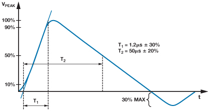 Figure 2: Level 4 is the highest specified ESD test under IEC 61000-4-2, with a contact-discharge voltage of ±8 kV and an air-discharge voltage of ±15 kV; the 8 kV contact-discharge current waveform has a rise time of under 1 nsec and pulse width of approximately 60 nsec, yielding a pulse with a total energy in the range of tens of mJ. (Source: Analog Devices, Inc.)The standard tests are closely matched to events such as ESD transients, among others. For example, IEC standard 61000-4-2 defines a pulse with specific rise/fall times and voltage levels, Figure 2. Vendors test and then guarantee that their devices will both withstand the pulse and provide protection against a pulse with these characteristics which, in turn, protects against a large class of over-voltage transients.
Using a component that provides sufficient protection is necessary but not sufficient to actually protect the circuit or system, as the component must be properly placed, of course—and that means more than just its placement on the schematic diagram. The mechanical specifics of where the device is placed and how it is installed are equally important. If the wires or PC-board tracks leading to a protection component are spaced too closely to adjacent unrelated wires, for example, the high voltage can "flash over" to those wires before the protection function activates and clamps the voltage to a safe level.
The issues related to proper placement and routing increase as the voltage/currents to be protected against also increase. For this reason, it is important to study vendor application notes, review regulatory guidelines on required or best practices, and even consider using a consultant. You do not want to submit an end-product for regulatory approval only to find out that your particular implementation of protection does not meet mandates; this is like building a house that is functionally perfect and then having the inspector inform you that you have many violations of the new building codes. Figure 3: Even with a "right" protection component there are critical issues of physical installation, location and layout; various standards define minimum creepage and clearance values for different operating-voltage levels. (Source: PCB Design Tech Guide)
Protection gets active
Traditionally, circuit-protection devices have been entirely passive for two reasons: the outstanding, verified reliability of such "simple" devices; and the lack of suitable active options. The situation is changing, as protection needs have increased in scope, as active devices with suitable topologies have been developed that meet these needs, and as the shortcomings of passive devices in some applications have become unacceptable.
 Figure 4: The LTC4539 Ideal Diode Controller with Reverse Input Protection is an example of how active components can provide the benefits of a conventional circuit-protection component, such as a Schottky diode), but without its drawbacks. (Source: Linear Technology Corp.)One good example is the need for reverse-voltage protection in automobiles, where the battery may be connected backwards by mistake or the DC-power leads accidentally "brush" against the wrong terminals. Decades ago this would not have caused damage, as there were little or no electronics in the car; the various electrical devices—such as the starter, window motors or lamps—could withstand reverse voltage to a large extent.
 Figure 5a: The forward-voltage diode drop of the LTC4539 is far lower than that of the Schottky diode; a reduction of even a few tenths of a volt yields major performance benefits. (Source: Linear Technology Corp.)
This situation has changed with the proliferation of complex electronic circuit boards in the car, providing infotainment, connectivity, ADAS (advanced driver assistance systems) and safety functions. The result is that designers of these circuits must also provide protection for each board or function. The obvious way to do this is by using a diode, but there is a severe electrical cost in the diode drop (0.3 to 0.8 V), diode dissipation (a function of current level) and other factors.
A better solution is an active circuit such as the LTC4539 Ideal Diode Controller with Reverse Input Protection from Linear Technology Corporation. When used in conjunction with a few external components, Figure 4, the configuration functions as a near-ideal diode with greatly reduced forward-voltage drop and dissipation, Figure 5a and Figure 5b. When the rail voltage is reversed, it cuts off the current flow within microseconds, before any damage occurs.
Conclusion
The world of circuit-protection devices is diverse and potentially confusing. Yet it is also one that it is essential to investigate and understand, because protection of various types and at  Figure 5b: As a consequence of the lower voltage drop, the LTC4539's dissipation is also far less than it would be with a Schottky-diode solution. (Source: Linear Technology Corp.)various points is critical to reliability and avoiding failures in products ranging from small, handheld devices to large instruments and machinery. No single device is the all-purpose solution, and many designs require more than a single protection device to meet performance and regulatory requirements. By working closely with vendors and using their applications' expertise, designers can develop effective solutions to the circuit-protection challenge.
References