 Take a look at some of the freeware available to aid engineers in developing designs.
Electronic design automation (EDA) is a category of software tools helping engineers correctly design printed circuit boards (PCBs) and integrated circuits (ICs). Whether you are an individual engineer who does not need a complicated tool to help you capture your design concepts, or you are part of a large design team in need of professional-class EDA software—either way there are a great many choices at your disposal, minimizing the prototype development process and allowing you to focus on design creation.
The fashion designer Coco Chanel once said, “The best things in life are free. The next best things are very, very expensive.” In a sense the same might be said for design tools. A recent evolution of design tool development is the online availability of free PCB design software from electronics distributors. In the listing that follows you’ll find free tools from such global distributors as Premier Farnell, RS Components, Digi-Key and Mouser Electronics.
There is also, of course, a not-so-free element. Obviously freeware will not do if you are designing complex, multi-function chips (or Systems-on-Chip), which absolutely require advanced design tools to validate concepts, model the behavior of a design, and analyze the complex interactions of constituent parts to ensure completeness, correctness and manufacturability of the final product. These types of tools are available from large EDA companies such as Cadence, Mentor Graphics, Synopsys and others. We will explore these tools in a follow-up article.
Here, however, we present free tools that generally can do schematic capture, Spice simulation and PCB layout. While free tools bring many of the benefits that high-end tools offer without unnecessary features and thus cost, in some cases they will have limitations, such as the number of components or pins allowed. Where the tools listed are limited versions of more expensive software we will tell you in what ways the free version of the software has been restricted compared to the commercial version.
Let us now take a look at some of the freeware available to aid engineers in developing designs (listed alphabetically).
Cadsoft Eagle Light Edition
http://www.cadsoft.de/download-eagle/eagle-freeware/
Cadsoft is owned by the global distributor Premier Farnell. Its EAGLE (Easily Applicable Graphical Layout Editor) PCB design software has three main modules (a schematic editor, layout editor and autorouter) and a common interface. EAGLE Light Edition, the free version of EAGLE, is ideally suited for small, simple schematics and is aimed at those who wish to evaluate the basics of EAGLE. The freeware is restricted in terms of EAGLE functions, however, limiting schematic sheets (two), board size (100 x 80 mm) and signal layers (two, top and bottom). In addition, once you begin to use the freeware version for commercial projects (earning income) you must purchase a license. Use in a commercial environment is allowed as long as it is only a matter of evaluating the program. Any files created with the freeware version of EAGLE Light can be used with any registered version of EAGLE Light, Standard or Professional. The freeware version of EAGLE may be redistributed with Linux distributions, software collections or project CD-ROMs.
CircuitMaker
CircuitMaker, built by Altium, is targeted at anyone just starting to get into PCB design. It is a free-to-use schematic and PCB design tool for the Open Source Hardware community. Hardware designed with it may be used for commercial and non-commercial purposes without limitation. There are also no limits on layer counts or board area. The software includes hierarchical schematic entry, autorouting and Native3D capabilities. CircuitMaker implements schematic capture and PCB design using the same engine as Altium Designer. The schematic editor includes basic component placement and circuit design as well as advanced multi-channel design and hierarchical schematics. All schematics are uploaded to the Altium server and can be viewed by anyone with a CircuitMaker account. CircuitMaker is interfaced to the Octopart database and search aggregator, which allows users to search across hundreds of distributors and manufacturers. It allows drag and drop placement of components from the Octopart search results.
DesignSpark PCB
http://www.rs-online.com/designspark/electronics/eng/page/designspark-pcb-home-page
DesignSpark PCB from the distributor RS Components is specially designed for Rapid Prototyping and turning circuit ideas into testable boards. It can be used for schematic capture, PCB board design and layout. As opposed to cut-down versions of a costly product or one with a time-limitation on license, DesignSpark PCB is offered completely free of charge and is fully featured without intentional limitations on board size, pin counts, layers or file output. There are unlimited schematic sheets per project, up to 1m2 of board size and no limits on layers. It offers access to an online library of more than 80,000 parts, instant Bill of Materials (BOM) quoting and links to fast turnaround PCB vendors through unrestricted Gerber and ODB++ outputs. It is written for the Windows platform.
Digi-Key CAD Tools
http://www.digikey.com/en/resources/design-tools/pcbweb
Distributor Digi-Key provides engineers with a set of free, online CAD tools to support PCB design and development. PCBWeb is an online CAD application for designing and manufacturing electronic circuit boards that aims to help engineers move projects from the earliest stages all the way through to a finished hardware design, ready to send off for production. Features include Schematic Capture (supports multi-sheet designs), PCB Layout (supports multi-layer boards as well as DRC) and a Component Editor (creates symbols and footprints). Using PCBWeb you can place Digi-Key parts into designs and manage those parts using the BOM editor. Other free resources from Aspen Labs and Digi-Key include Scheme-it, which is a basic online circuit design tool to simplify Schematic Drawing and Block Diagramming. The tool includes a comprehensive electronic symbol library and an integrated Digi-Key component catalog that allows for a wide range of circuit designs. Scheme-it works natively in all major web browsers without requiring the use of any plugins. Only registered users are able to share and save designs. PartSim is a more advanced circuit design utility that offers tools such as a full Spice simulation engine, a web-based schematic capture tool and a graphical waveform viewer. PartSim also includes an integrated BOM manager that lets you assign Digi-Key part numbers to your models.
EasyEDA
Aimed at electronic engineers as well as hobbyists, EasyEDA is a free, Web- and Cloud-based EDA tool suite integrating schematic capture, Spice simulation and PCB layout in a browser environment. It has over 70,000 schematics in its web database along with 15,000 Spice libraries. The accompanying website offers numerous projects and electronic circuits made by others (it is public and open hardware). Designs can be imported from Eagle, Altium, KiCad and LTspice. Mac, Linux, Windows and Android platforms are all supported.
FreePCB
FreePCB is a PCB design program running on Microsoft Windows. It is released under the GNU General Public License. Designed to be easy to learn and easy to use, yet it is capable of professional-quality work. FreePCB does not have a built-in autorouter, but it can use the FreeRoute web-based autorouter at www.freerouting.net. Some of its features are: 1 to 16 copper layers; board size up to 60 inches by 60 inches; Footprint Wizard and Footprint Editor for creating or modifying footprints (footprint libraries are courtesy of Ivex Design International and PCB Matrix); and it exports PADS-PCB netlists as well as extended Gerber files and Excellon drill files.
gEDA
Tools in the gEDA project are used for electrical circuit design, schematic capture, simulation, prototyping and production. The free software includes schematic capture, attribute management, BOM generation, netlisting into over 20 netlist formats, analog and digital simulation, and PCB layout. It is targeted at designs of low- to mid-level complexity. Using the gEDA tools, you can create a PCB of up to eight layers with an unlimited number of components and nets. The tools are suitable for use by hobbyists, but also in cases where an engineer needs to turn out a PC board in a hurry. The suite is mainly being developed on the GNU/Linux platform. Tools for PCB layout and manufacturing include: gschem (a schematics editor), pcb (for PCB layout), gerbv (a Gerber viewer), wcalc (for transmission line and electromagnetic structure analysis), and mcalc (a Microstrip Analysis/Synthesis Calculator).
KiCad
KiCad is an open-source software suite. The free programs, licensed under GNU GPL General Public License v3, handle Schematic Capture (a library of schematic symbols and a built-in schematic symbol editor helps you get started quickly); PCB Layout (for up to 32 copper layers); a Gerber file viewer; and a 3-D viewer that you can use to rotate and pan around to inspect details that are difficult to inspect on a 2-D view. CERN—yes, the people behind that large particle collider in Switzerland—contributed to the KiCad project by adding features to the module editor, which is used to create footprints for parts. The CERN addition includes support for DXF files, which makes it easy to import part drawings or use external tools for more complex designs. CERN also added differential pair routing and trace length matching to KiCad capabilities. These features enable engineers to more easily design PCBs that support fast signals over a long distance and with less noise. The KiCad suite runs on Windows, Linux and OS X.
MultiSIM Blue from Mouser
http://www.mouser.com/multisimblue/
MultiSIM Blue is a free online simulation tool from the distributor Mouser Electronics. It lets engineers go from schematic capture to circuit simulation, to PCB layout to BOM and purchase, in one integrated tool. Created in collaboration with automated test company National Instruments, it offers functional simulation of linear circuits using the Berkeley SPICE Engine along with a preloaded component library of over 100,000 frequently used components from multiple Mouser databases, including analog, mixed-signal ICs, passives, discrete components and electromechanical parts. Limitations imposed on this version of MultiSIM compared to the Power Pro version include a maximum of 50 parts on a board, and in the original version of Blue only two custom parts per design (which cannot be saved to a parts database for reuse via copy- and-paste to another design). The latest version of MultiSim Blue increased the number of custom components to six. MultiSIM Blue also provides a 3-D visualization of the PCB with no limits on the shape and size of the PCB.
ZenitPCB
ZenitPCB is a free PCB design software tool for personal or semi-professional use limited to 800 pins. Zenit PCB has two parts: ZenitCapture Schematic and Zenit PCB Layout. A schematic in ZenitCapture can have several pages and can lead to a layout by a Netlist File (ASCII). Devices are selected from the part libraries, or new devices are created on the schematic parts editor. With ZenitPCB Layout it is possible to create the project starting from either the schematic capture or from the layout itself. In the first instance you can import a netlist (file ASCII containing electrical info) from different schematic capture (Orcad, Pads, Multisim, Protel, Eagle, and so forth), with all the components and the relative electrical connections. In the second instance you can realize your project directly from the layout editor, importing components from the library, and connect the pins directly with the cursor. Using the button “Open GerberView” you can open the program ZenitPCB GerberView, and it will show you the Gerbers according to the ASCII file.
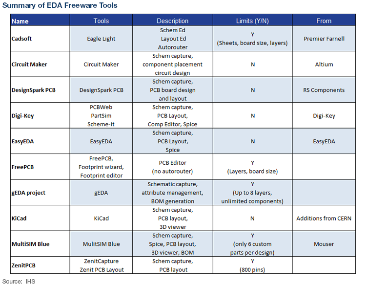 Table 1: Summary of EDA Freeware Tools
