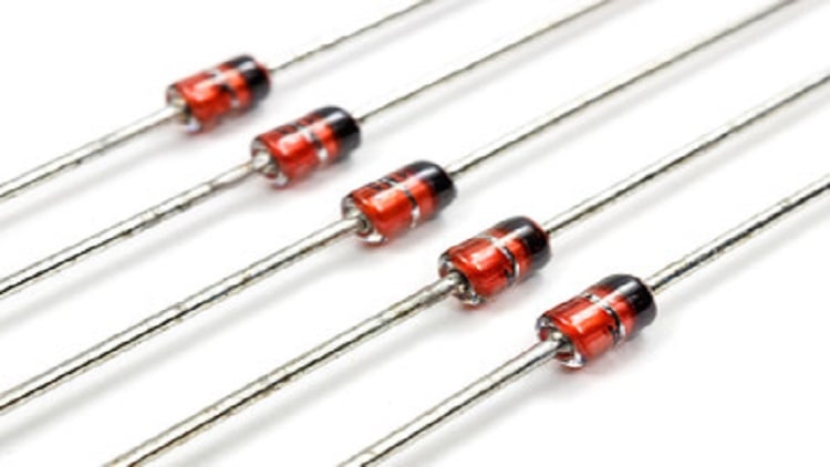
Diodes are among the simplest but most useful semiconductor devices used in a broad range of applications today. They are basically two-terminal components that allow an electric current to flow in one direction within an allowable voltage range.
However, diodes come in different types and can be configured in several ways to meet the requirements of an application.
Understanding how diodes work
Diodes can be represented in an electric circuit using the symbol in Figure 1, with the arrow representing the direction of current flow.
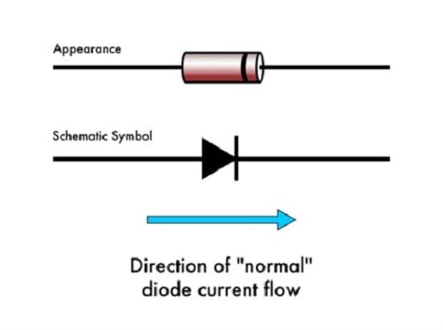 Figure 1: Diode symbol showing the direction of current flow. Windell Oskay/CC SA 2.0
To better understand how diodes work, consider Figure 2. It represents a check valve used in pneumatic or hydraulic systems to ensure fluid flows in only one direction.
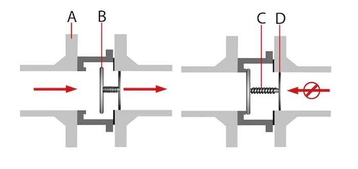 Figure 2: Check valve used in pneumatic or hydraulic systems. Source: Tameson
It can be observed that when fluid pressure is at the left end of the valve’s gate, it pushes against the gate. This force opens the gate, allowing fluid flow. In contrast, when the pressure direction is reversed, it pushes the valve’s gate shut and prevents fluid flow. As a result, fluid flow can only occur from the left end of the gate toward the right end.
Diodes in electrical circuits act similarly to check valves. For instance, the voltage in a circuit is similar to the pressure in the check valve, while the flow of electric charge (or electric current) is similar to fluid flow. Therefore, a diode is essentially a voltage-operated device that allows the flow of electric charge in one direction. It has a high electrical resistance on one end and a negligible resistance on the other, causing current to flow toward the end with low resistance. The amount of voltage needed to get current to flow across a diode is called the forward voltage.
The PN junction diode
The PN junction diode is the simplest form of semiconductor diode. It operates like an open circuit in the reverse direction and a short circuit in the forward direction. It features a p-type semiconductor and an n-type semiconductor combined to form a p-n junction, as shown in Figure 3.
 Figure 3: PN junction diode. Source: Raffamaiden/CC SA 3.0
At the p-n junction, a depletion region is formed through which excess electrons move from the n-type semiconductor to occupy the holes in the p-type semiconductor region.
Forward-biased diode
In a forward-biased diode, the battery’s positive terminal is connected to the p-type side, while the negative terminal is connected to the n-type side of the diode. As a result, when the externally applied voltage across the diode is more than the diode’s forward voltage, the depletion region collapses. This collapse causes the diode to act as a short circuit, allowing current to pass through it.
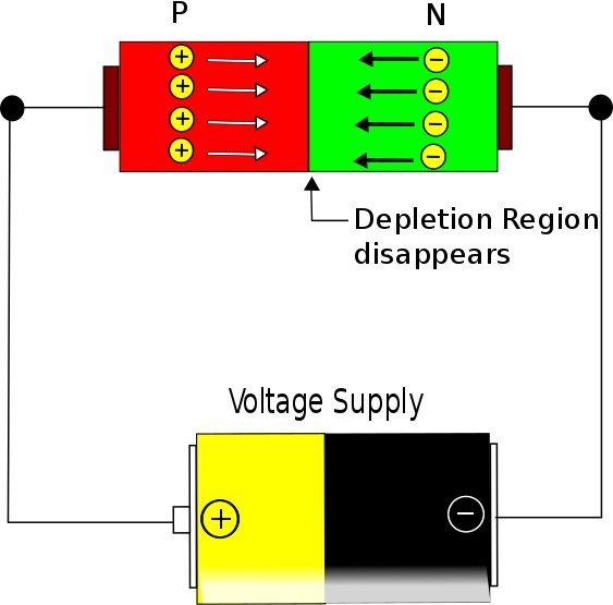 Figure 4: PN junction depletion region collapses in a forward-biased diode. Source: A.K. Kartheeikeyan/CC SA 3.0
A diode's forward voltage value varies depending on the material used. For instance, silicon diodes typically have a forward voltage of 0.7 V, while germanium diodes typically have a forward voltage value of 0.3 V.
Reverse-biased diode
In a reverse-biased diode, the voltage source polarity is reversed so that its positive terminal is connected to the n-type side of the diode while the negative terminal is connected to the p-type side of the diode. This causes more holes to be pulled toward the negative terminal of the source while the electrons are pulled more toward the positive terminal. As a result, the diode’s depletion region widens, resulting in increased electrical resistance and causing the diode to act as an open circuit.
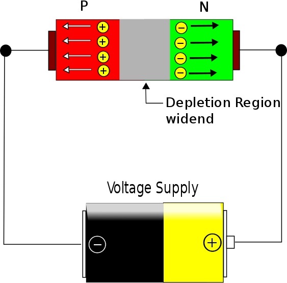 Figure 5: Reverse-biased diode. Source: A.K. Kartheeikeyan/CC SA 3.0
Diode equation
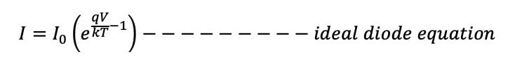
The diode equation expresses the current flowing through a diode as a function of the voltage applied across its terminals. It is given as:
Where:
I = diode current (in Amperes)
Io = dark saturation current in Amps
q = Euler’s constant (approximately 2.71828)
V = applied voltage across the diode terminals
k = Boltzmann’s constant (1.38 × 10⁻²³)
T = absolute temperature (K)
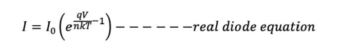
However, this diode equation only represents an ideal scenario. In reality, an ideality factor (n) is added to the equation, which measures how closely a diode follows the ideal diode equation.
Learn more about diodes on Globalspec.com.
Conclusion
While this article covers the basics of a PN junction diode, several other diodes variants are available today. For instance, Zener diodes, rectifier diodes and Schottky diodes have different constructions and suitability for different application needs. Therefore, engineers are advised to reach out to diode suppliers to discuss their application needs.
