The mechanical gyroscope that uses a spinning rotor has been largely "spun down" by an electro-optical approach, which has no moving parts and no 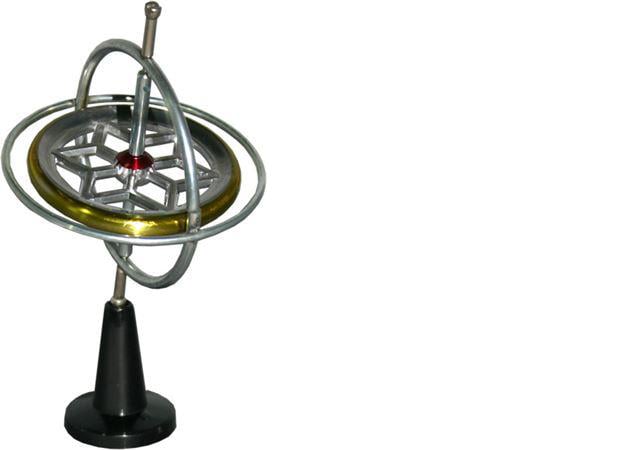 need for a gimbaled platform. Although a high-end rotor-based gyro is still the most precise gyroscope available, the fiber optic gyroscope (FOG) is capable of performance that is nearly as good and more than adequate for many applications—with lower cost, size, power, maintenance needs, and fragility.
The FOG is not just a different design using a different core gyroscope component to determine acceleration, velocity and distance in real time. [Keep in mind that velocity is the integral of acceleration and distance is the integral of velocity; thus, once you know acceleration, you can determine the two other factors.] Instead, the FOG approach enables a different implementation of the entire gyro platform and overall guidance/navigation system.
A Literal Change in Platform
With a traditional rotor-based gyroscope, the gyro is mounted on a gimbaled platform that is used to establish a fixed inertial reference frame, which does not change its orientation in space even as the vehicle (aircraft, rocket, submarine) accelerates or rotates. An orthogonal set of triaxial accelerometers and rotary transducers around the spinning core comprise an inertial measurement unit (IMU) used sense. They report the motion of the vehicle relative to this fixed-in-space platform, with the IMU outputs used to derive the velocity and position information. From the point of view of the gyroscope, the vehicle is moving around it as it maintains this inertial reference orientation.
The entire spherical gyroscope assembly ranges in size from a few centimeters (cm) to about 25 cm in diameter, and is mechanically extremely complex. It requires the most advanced and precise mechanical components, especially for the bearings of gyro rotor and the platform gimbals (note that an aircraft or spacecraft needs a gimbal with three degrees of freedom, while a surface vessel may only need two degrees, which significantly reduces complexity, cost, error potential and size).
In contrast, the FOG offers two distinct differences and advantages. First, it uses counter-rotating beams of light circulating in an optical fiber, and so eliminates moving parts. While it also needs precision components and alignment of the light source, half-silvered mirror and other parts, this is an easier type of precision to achieve and maintain than with rotating mechanical system.
More importantly, the FOG is a "strap-down", non-gimbaled instrument and is rigidly attached to the vehicle, and thus moves and turns with it. In sharp contrast to the rotor-based gyro, it does not provide a fixed, inertial reference in space. Instead, it reports on its own motion, which is also the motion of the vehicle. The data it presents about its motion is used by a dedicated processor (which is a separate chassis) to compute absolute-motion parameters; this is a process that requires a substantial amount of real-time calculation.
Why bother with a gyroscope when GPS signals are available, and low-cost, high-performance GPS chipsets are commonplace? There are several reasons: GPS does not work in tunnels, underground (oil wells), inside buildings, or underwater; it is susceptible to deliberate interference and jamming, as well as unavoidable outbursts from solar events that overwhelm the GPS signal; and it takes about a minute to deliver the first valid position fix, which may be unacceptable delay in some situations.
From Theory to Implementation in Just 75 Years
The principle on which the optical gyro is based was first observed by physicist Franz Harress in 1911 and recognized by Georges Sagnac in 1913; for various reasons, it is always referred to as the Sagnac effect. It is a consequence of the legendary Michelson-Morley experiment (1877), which used an optical interferometer to show that there was no "ether" through which the Earth traveled in space. The absence of this ether, which was an attempt to explain various optical phenomena and anomalies, was among the factors that led Einstein to make his radical, highly counterintuitive supposition that the speed of light was constant, regardless of any motion of the source of observer.
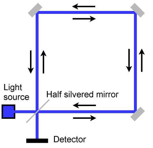 The schematic representation of a Sagnac interferometer shows how a single light source is split into counter-rotating optical beams, which recombine at a detector that senses their interference fringes and their motion.In the basic demonstration of the Sagnac effect, a polarized beam of light is split by a half-silvered mirror into two beams, which travel around a square path in opposite directions, with the beams turned at the corners by mirrors. When the beams recombine at the source, their interaction will yield interference fringes. If the interferometer does not rotate, these fringes are stationary. However, if the unit does rotate, one light beam travels a shorter distance in relativistic sense than the other, causing the interference fringes to shift. This shifting is sensed by an optical detector, with the amount and rate of this shifting is directly related to the interferometer's acceleration (rotation is an acceleration vector).
Building a practical and precise gyroscope using the counter-rotating beams has its own challenges, of course. The first such implementation, called a ring laser gyro (RLG), used an evacuated (vacuum) path acting as an optical waveguide. Typical path length was a just few meters, which affected accuracy; combined with the mechanical fragility, this limited the uses of light-based gyros due to cost, size, and maintenance issues.
This situation changed with the development of low-loss, high-performance optical fibers. This is yet another example of one application taking advantage of developments driven by other applications; in this case, communication links based on optical fiber. The fiber optic gyro uses these hair-thin fibers as the waveguide rather than a vacuum path. It is far less fragile, eliminates the mirrors needed for 90⁰ corner turns and is more easily interfaced to a laser-diode light source.
The fiber-based gyro has one other major advantage compared to the ring laser design; the optical fiber can be tens or even hundreds of meters in length and coiled up in the final assembly, rather than the roughly several-meter path length and boxy overall volume of the ring laser design. As is the case in most test and measurements applications, a longer baseline of time or distance yields more accurate measurements.
As with most real-world systems, the difference between achieving "pretty good" and "really good" performance is in the design's details, error 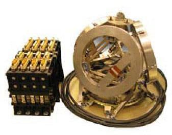 Each coil of the Astrix 200 FOG from Airbus Defense and Space.x 200 FOG from Airbus Defense and Space, with resolution of 0.001 arcsec, has 5 km of optical fiber analysis and final execution. The FOG output reading's consistency and precision are affected by factors such as temperature-induced drift in the assembly; temperature gradients across the fiber; non-linearities in the fiber dispersion and at the fringe detector; noise of various sources and types; and many other subtleties. Even the mechanical strain on the fiber as it is wound into the small coil can induce phase shifts, signal dispersion, or polarization changes, all of which translate to errors.
To understand and minimize these errors, experts such as those at The Charles Stark Draper Laboratory (Draper Labs, Cambridge MA), a world-leading guidance-system research institution, analyzed FOG-performance factors and their first-, second-, and even third-order sources of error, then minimized them through basic design or computational algorithms. They also saw places where it is possible to take advantage of the presence of two nominally identical light beams that have opposite rotation, in order to make some errors to cancel themselves out, which is always an attractive error-reduction technique. As a result of these efforts, the FOG's design and implementation were refined to where its performance is close to the more-complex traditional spinning-rotor gyro.
Even the specifics of the fiber affect performance. One vendor, KVH Industries, even makes its own fiber with an elliptical cross-section rather than use the standard communications fiber, which has a circular cross section, because of some polarization issues with the latter. The sensitivity of the FOG depends partially on fiber length and diameter, with longer, thinner fibers providing a better, clearer indication of rotation rate. However, it has tradeoffs in signal strength (signal/noise ratio) and dispersion compared to shorter, thicker fibers.
The viability and performance of the FOG are proven by its widespread applications. It has been the standard navigation gyroscope on commercial airlines since the late 1980s (and GPS is now also on these aircraft, for cross-checking of position). The algorithms that are executed in the FOG’s physically separate electronics chassis can compensate for many errors and also integrate GPS data. A compact single-axis FOG costs just several thousand dollars, provides basic accuracy to 0.05% and provides data for angular rates as low as tens of degrees per second and as fast as 500°/sec.
Even with its own many virtues compared to the rotor-based gyro, the FOG approach is under some competitive pressure. MEMS-based gyros and inertial measurement units can provide reasonably good performance in tiny, low-cost, low-power packages, with accuracy that is sufficient for many short-range applications such as drones and robots. While presently not accurate or consistent enough for long-range navigation, they may yet become the disruptive technology to the fiber-optic gyroscope, which itself largely displaced the rotor-based device.
To contact the author of this article, email engineering360editors@ihs.com
References
Michelson-Morley experiment:
"The Michelson-Morely Experiment," http://galileoandeinstein.physics.virginia.edu/lectures/michelson.html
"The Michelson-Morely Experiment: A Famous Experiment that "Failed," http://hyperphysics.phy-astr.gsu.edu/hbase/relativ/mmhist.html
The Sagnac effect:
"The Sagnac Effect," www.mathpages.com/rr/s2-07/2-07.htm.
"A Simple Description of the Sagnac Effect," http://www.physicsinsights.org/sagnac_1.html
"Sagnac Interferometer: Theory & Background," http://www.physics.rutgers.edu/ugrad/389/sagnac-interferometer.pdf
Ring laser and fiber optic gyroscopes:
"Precision Fiber Optic Gyros," KVH Industries, Inc., http://www.kvh.com/fiberopt/
"Ring Laser Gyro," www.fas.org/man/dod-101/navy/docs/fun/rlg.htm.
"High-performance fiber optic gyros no longer just a dream," SPIE Web, www.spie.org/web/oer/february/feb97/tebo.html.
Airbus Astrix FOG, http://www.space-airbusds.com/en/equipment/astrix-200.html
General references:
Donald MacKenzie, "Inventing Accuracy: A Historical Sociology of Nuclear Missile Guidance," MIT Press, 1990, ISBN: 9780262132589.
Anthony Lawrence, "Modern Inertial Technology," Springer, Second Edition, 1993, ISBN: 0-387-98507-7.
