Several electrical properties are essential for the operation of electrical products and systems today. One of these properties is the electrical resistance, which measures an object’s opposition to the flow of electric current. Electrical resistance limits the electric current to a safe value so that associated sophisticated parts can function properly.
Analog ohmmeters are devices used to measure electrical resistance in a circuit or a component. They typically feature two test leads (on which the component's terminals are connected) and a needle (or pointer) that deflects according to the component’s electrical resistance value. But how do analog ohmmeters work, and what are the different types available?
Understanding analog ohmmeters working principle
To understand how analog ohmmeters work, consider a simple ohmmeter circuit shown in Figure 1. This circuit features a 12 V source (battery) and an analog movement component with a 500 Ω movement resistance (meter resistance or internal resistance) and a full rating of 1 mA.
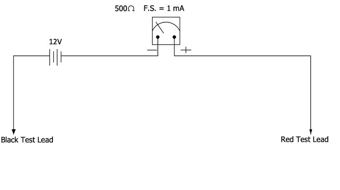 Figure 1: Simple ohmmeter circuit with the two test leads apart. Source: Temitayo Oketola
When the ohmmeter’s two test leads are apart, there is no current flow through the circuit. As a result, it could be said that the ohmmeter measures an infinite resistance, which is indicated by the pointer’s deflection toward the extreme left of the scale. Now when the two test leads are directly connected, there will be maximum current flowing through the circuit (see Figure 2).
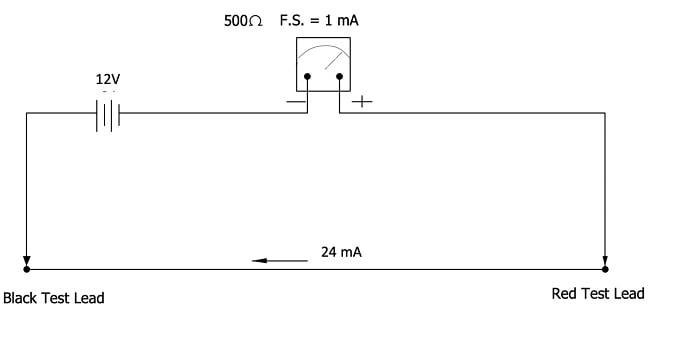 Figure 2: Simple ohmmeter circuit when two test leads are connected. Source: Temitayo Oketola
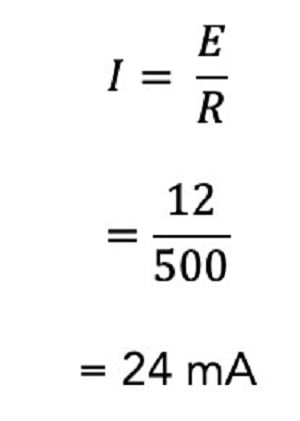
It could be said that the ohmmeter measures zero resistance, which is indicated by the pointer’s deflection toward the right side of the scale. As a result, this circuit will experience an electric current of 24 mA, as shown in the equation below.
This electric current value (24 mA) is far above the rating of this meter (1 mA) and will likely damage the meter. To solve this challenge and limit the current in the circuit to 1 mA, add resistance (in series) to the meter’s circuit, as shown below.
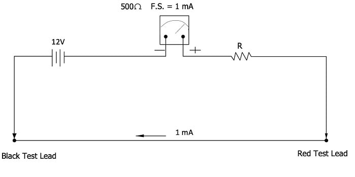 Figure 3: Series-type ohmmeter circuit. Source: Temitayo Oketola
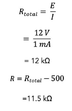
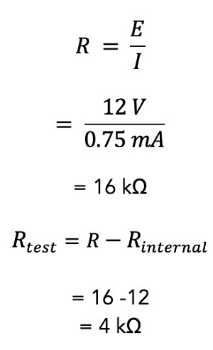
The required series resistance value that will limit the circuit current to 1 mA can be determined by calculating the total resistance of this new circuit and subtracting the meter’s internal resistance, as shown below:
Now that the ideal resistance has been calculated, this circuit could serve as an ohmmeter. However, one challenge still exists: the ohmmeter cannot accurately measure the resistance values of different components placed between its test leads. Instead, it only gives resistance values when the test leads are shorted or open. This challenge can be solved by calibrating the ohmmeter circuit.
[Discover more about analog ohmmeters on GlobalSpec.com]
Calibrating the circuit
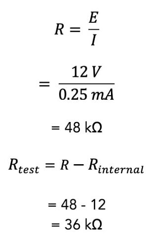
To calibrate this circuit, engineers will have to determine the resistance value between the test leads that will cause quarter-scale, half-scale and three-quarter scale deflections of the pointer. Since the full-scale rating current is 1 mA, the current flowing through the circuit during a quarter-scale deflection must be 0.25 mA. Therefore the total resistance for this circuit will be 48 kΩ, and a component with a resistance of 36 kΩ will cause quarter-scale deflection of the pointer, as shown below:
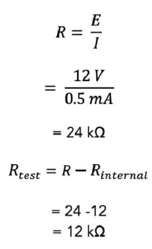
The amount of resistance that will cause a half-scale deflection of the circuit is 12 kΩ, as shown below:
Finally, the resistance value that will cause a three-quarter scale deflection of the pointer can be determined as follows:
Therefore, the ohmmeter scale for this particular scenario is shown in Figure 4 below.
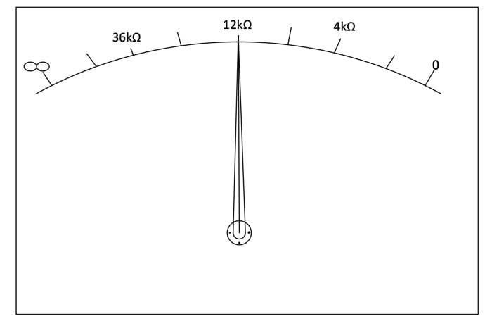 Figure 4: Calibrated ohmmeter scale. Source: Temitayo Oketola
However, keep in mind that this scale is nonlinear and often has poor accuracy. Therefore, multirange ohmmeters with mid-scale resistances are often desirable for measuring resistance values. Multirange ohmmeters are usually designed using meter mechanism shunts.
Shunt-type ohmmeter
Figure 5 shows a typical circuit for a shunt-type ohmmeter. In this circuit, the unknown resistance (Rx) is connected in parallel across the meter component through the test leads.
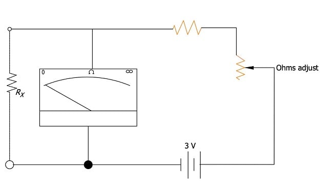 Figure 5: Shunt-type ohmmeter. Source: Temitayo Oketola
If the terminals of the test leads are shorted (i.e., Rx = 0), it causes all the current to be shunted away from the meter mechanism. This causes the meter mechanism to deflect toward the left of the scale to indicate 0 resistance. In contrast, high Rx values allow higher currents through the meter, causing the meter’s pointer to deflect to the right.
Notice how the scale of shunt-type ohmmeters is quite different from the series-type ohmmeters previously explained. For instance, full-scale deflection measures very high resistance in the shunt-type ohmmeter. In contrast, a pointer’s full-scale deflection in the series-type ohmmeters indicates zero resistance.
Shunt ohmmeters are ideal for measuring low resistance values (in the range of 5 to 400 Ω).
Conclusion
Ohmmeters are essential measurement devices used for many applications today. While this article presents helpful information about basic analog ohmmeters, several other types of ohmmeters provide better accuracy and a higher measuring range than analog ohmmeters. Therefore, engineers are advised to reach out to ohmmeter suppliers to discuss their application needs.
