Direction and fluid flow rate sensors are important for different industrial, medical and environmental applications. Flow sensors quantify the direction and rate of both gas and liquid flow in applications such as density measurements, viscosity measurement, flow pattern determination and wall shear stress determination. In addition to the vital demands of flow parameters for sensing range like direction, temperature, velocity and rate, the characteristics of various targeted liquids or gases to be detected are posing hurdles in designing accurate, low-powered and inexpensive sensors.
MEMS flow sensors
In recent years, microelectromechanical system (MEMS) technology has broadened opportunities for the production of flow sensors for different uses. MEMS was first suggested in the 1960s after a study of silicon and germanium piezoresistivity capacity. In the early years, MEMS flow sensors were built using both polymer and silicon components and by using different sensor components and construction methods. Thermal, drag-force and torque-based flow sensing are perhaps the most popular sensing techniques.
In this article, a thorough overview of the different nano/micro-scale MEMS flow sensors that have been built to date is presented. These three broad groups, based on their sensing theory, are MEMS piezoresistive, thermal and piezoelectric flow sensors.
Piezoresistive flow sensors
The elements that show resistivity changes when influenced by external strain or stress are known as piezoresistive materials. The material’s internal lattice and atomic positions are changed due to this applied strain, and therefore, its resistivity is also changed. Manufacturers are widely using piezoresistive materials for developing MEMS flow sensors. They have gained attention for flow sensing because of their capability of changing the resistance when stress is applied. When used in MEMS flow sensors, the resistance change is mapped to a voltage signal that fluctuates as the velocity of flow changes.
MEMS thermal flow sensors
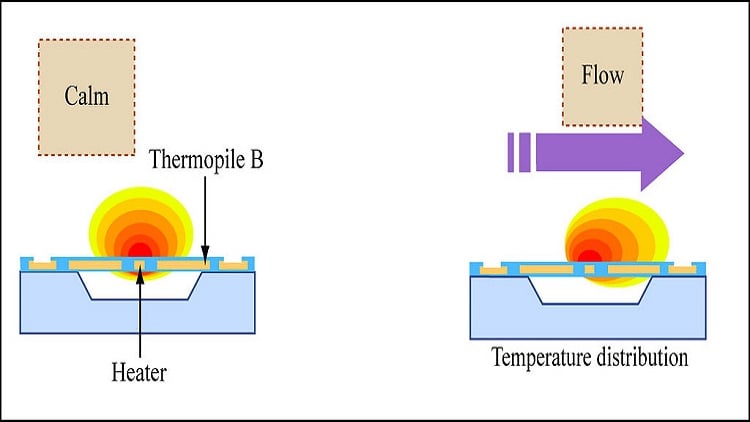
The flow sensors that use intensity of transfer of heat to measure the velocity of flow are known as thermal flow sensors. The phenomenon guarantees greater precision and sensitivity in readings taken with small output signal drift. Furthermore, the benefit of such sensors is that they can function with no need for physically shifting any micro-parts. MEMS thermal flow sensors generally consist of two primary components: sensing and heater elements. The heat transfer difference between the working flow and heater is sensed by the sensing element, so the system’s sensitivity increases as extra heat energy is transmitted to the functioning fluid.
One of the key constraints affecting the precision of the standard temperature-based flow sensors tends to be the proper preservation of the temperature of the sensing component. The failure to calculate low flow velocities is another problem related to MEMS thermal flow sensors. The sensing components in conventional hot-film and hot-wire sensors have a large specific heat capacity, which makes it difficult to track the low convectional heat transmission leading to low or bad frequency response.
There are three kinds of MEMS thermal flow sensors identified in light of the various heat management methods and different assessment methods. H-type sensors are the first kind. These are hot-film and hot-wire sensors that calculate the flow by adjusting the power of heat at a steady temperature or adjusting the temperature at steady power of heat. The distinction among them is attributable to their construction: the wire resistor in hot-film sensors is placed on a membrane next to the flux, whereas the resistor is independent of the substratum and located inside the flow in hot-wire type H sensors. C-type sensors, the second type, are calorimetric sensors that measure the flow by measuring heat profile changes across the heater. Time-of-flight sensors are the third category that measures flow via heat pulse recognition at a given distance from the heater.
MEMS piezoelectric flow sensors
Certain artificial and natural dielectric materials have the property of piezoelectricity, which allows them to generate electric charges when a mechanical load is applied. This is also called the direct piezoelectric effect. On the other hand, if such materials are exposed to external electrical fields, dimensional or geometric changes are influenced. This effect is referred to as the converse piezoelectric effect. A major piezoelectrical effect is illustrated in polymers like polyvinylidene fluoride (PVDF) and polycrystalline ferroelectric ceramics including barium titanate (BaTiO3) or lead zirconate titanate (PZT). MEMS piezoelectric flow sensors are automatic and thus don't need an external power source to achieve the sensor output signal. Furthermore, they are mostly made up of polyvinylidene difluoride (PVDF) and lead zirconate titanate (PZT) materials.
Applications
MEMS flow sensors have a variety of uses, such as sensing environmental flow, flow monitoring of industrial gas, flow sensing in biomedical applications and marine hydrodynamic sensing. MEMS flow sensors' compact size, high sensitivity, low price and batch production functionality make them highly appealing for commercial and industrial applications. Moreover, a few of the MEMS soft polymer sensors are biocompatible and open the door for marketing in clinical and biomedical applications.
MEMS flow sensors are increasingly in demand for therapeutic respiratory flow sensing tasks in areas such as ventilators, nebulizers, oxygen systems and sleep apnea diagnostic instruments. Wearable breathing monitors with integrated MEMS flow sensors have the ability to track rates and speeds of flow. They are popularly being used for monitoring the performance and recovery of athletes. Moreover, in the flow velocity tracking in intravenous infusion, MEMS sensors will play a key part in enabling effective drug distribution for gravitational injections and preventing unintended incorrect medications that could be triggered by infusion-pump defects.
