Direct current (DC) supply and capacitors form the basis of several capacitive circuits in a broad range of equipment today. For instance, when DC voltage is applied to a capacitor, the capacitor draws current from the supply and charges up to a value of the supply voltage.
However, capacitors behave differently when connected to an alternating current (AC) source. They oppose the flow of AC; the measure of this opposition is called capacitive reactance.
But how does capacitive reactance compare to electrical resistance, and what are its applications and effects on electric circuits?
Understanding capacitive reactance
Consider Figure 1, which shows the variation of alternating voltage and the current flowing through the capacitor.
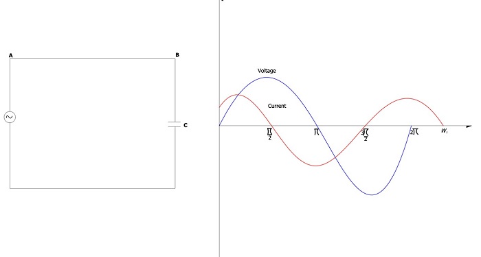 Figure 1: Variation of alternating voltage and the current flowing through a capacitor. Source: Temitayo Oketola
As Figure 1 demonstrates, the voltage and current of an AC supply frequently change at a rate determined by the frequency of the AC supply. When a capacitor is connected to such a circuit, the capacitor continually charges and discharges as the AC voltage reaches its maximum and minimum values. As the capacitor charges and discharges, the electric current that flows through it is restricted by the internal impedance of the capacitor. This internal impedance is the capacitive reactance of the capacitor.
Capacitive reactance is measured in Ohms (Ω) and can be calculated using:
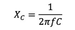
Where:
f = frequency (Hz)
C = capacitance (F)
As the equation demonstrates, the capacitive reactance increases as the capacitance declines. In addition, the higher the frequency by which the current alternates, the lesser the capacitive reactance. For instance, consider a 220 nF capacitor at 18 kHz and 20 kHz frequencies. The capacitive reactance will be 40.18 Ω and 36.17 Ω, respectively.
What is the difference between capacitive reactance and electrical resistance?
Capacitive reactance and electrical resistance are electrical properties that oppose current flow. However, they differ because electrical resistance opposes current flow (AC or DC) in conductors and resistors, whereas capacitive reactance applies to capacitors and is specific to AC power.
In addition, the reactance of a capacitor is inversely proportional to the frequency, while electrical resistance remains constant as the frequency changes.
Two common applications of capacitive reactance
1. Low pass filter
A low pass filter is a circuit that is designed to reject high frequency signals and attenuate (or accept) those signals at low frequencies wanted by the circuit designer. Simply put, these circuits filter out unwanted high-frequency signals.
Low pass filters are constructed using a simple resistor-capacitor (RC) circuit. In such a circuit, the resistor is placed in series to the input signal (or AC voltage source, Vin) while the capacitor is placed in parallel to the input signal. The output signal (Vout) is taken across the capacitor, as shown in the figure below.
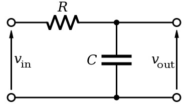 Figure 2: Low pass filter. Source: Inductiveload/Public domain
As mentioned previously, capacitive reactance is inversely proportional to the frequency, while electrical resistance remains constant as the frequency changes. Therefore, the capacitor’s capacitive reactance will be very large at low frequencies compared to the resistor’s resistance value. As a result, the voltage potential (or Vout) across the capacitor will be much larger than the voltage across the resistor. In contrast, the voltage across the capacitor at high frequencies is small compared to the voltage across the resistor.
Look at it this way. The capacitor in a low pass filter acts as a short circuit at high frequencies, resulting in a zero output in the output terminals of the circuit and blocking signals.
[Learn more about low pass filters on Globalspec.com.]
2. High pass filter
A high pass filter, also known as a differentiator, filters out unwanted low-frequency signals and accepts the high-frequency signals.
Like the low pass filter, high pass filters use an RC circuit. However, in a high pass filter circuit, the capacitor is placed in series to the input signal (or AC voltage source, Vin) while the resistor is placed in parallel to the input signal (see Figure 2). In addition, the output signal (Vout) is taken across the resistor.
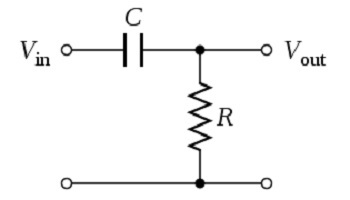 Figure 3: High pass filter. Source: Vadmium/Public domain
In this high pass filter circuit, the capacitive reactance is high at low frequencies and acts as an open circuit, blocking low input signal. In contrast, at high frequencies, the reactance becomes low, and the capacitor acts like a short circuit, allowing input signals to pass to the output. High pass filters are commonly used in audio amplifiers.
Summary
RC circuits are used in a broad range of applications today. However, the performance of these circuits depends on engineers selecting the ideal resistor and capacitor components for their application needs. Learn more about the selection criteria for capacitors and resistors.
