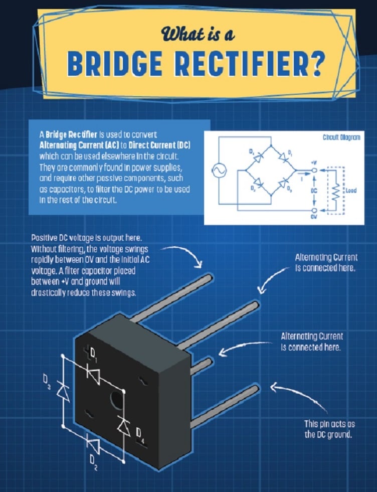
A bridge rectifier is used to convert alternating current (AC) to direct current (DC), which can be used elsewhere in the circuit.
This type of full-wave rectifier uses a standard transformer and four diodes in a bridge configuration. The bridge configuration of the diodes is what allows it to rectify the full AC wave without using a center-tapped transformer like a standard full-wave rectifier. Instead, bridge rectifiers use a standard transformer, reducing the cost of the circuit.
In the diagram above, the positive DC voltage output is located at a top pole. Without filtering, the voltage swings rapidly through poles between the output voltage and the initial AC voltage. A filter capacitor placed between the plus voltage and ground will drastically reduce these swings. Two poles on opposite sides connect the alternating current, a bottom pole acts as the DC ground.
[Browse suppliers of power rectifiers and learn more about this technology on GlobalSpec]
These components are commonly found in power supplies and require other passive components, such as capacitors, to filter the DC power to be used in the rest of the circuit.
