This article is for those who are interested in learning about the fundamentals of DC motor control in electronic systems. The most prevalent form of the motor is a direct current (DC). There is nothing simpler than plugging a battery's wires into the two terminals of a motor, and it will start to rotate in a certain direction. Switching the leads will cause the motor to turn in the other direction. Because the battery can't be too powerful for the motor, it's a little trickier, but it's still possible! If not, there's a chance the motor will get destroyed. However, the difficulty is that it just rotates, and as there is also no way to control the speed. In order to change orientation, each of the wires must be manually inverted.
Fortunately, both the speed and direction of a DC motor can be controlled via an Arduino microcontroller. Let’s get into details.
Direction control
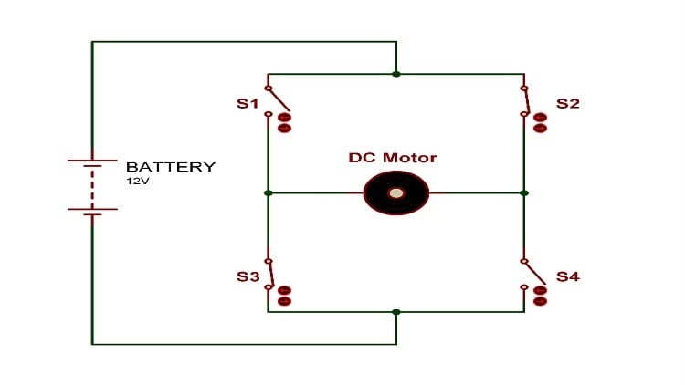
A circuit known as an H-bridge may be used to alter the direction of rotation of a DC motor without altering the way the leads are connected. These have four switches that may be opened and closed to apply the voltage in a certain direction, allowing the motor to change its direction as per requirements. When it comes to controlling robot motion, H-bridges are the most prevalent choice. The H-bridge gets its name from its four-transistor configuration — it appears as an "H" on a schematic diagram.
A DC motor is located in the middle of the horizontal bar of the H in the example given in Figure 1. Two switch configurations are possible to make the DC motor spin in the desired direction. In the first setup, switches 1 and 4 are closed and the corresponding switches 2 and 3 are open. In the second configuration, S1 and S4 are open, while the other two are closed. Any other switch arrangement would cause the motor to stall, or worse, cause a short circuit in the power supply. In either case, the motor would be rendered unusable.
Discrete transistors or metal-oxide-semiconductor field-effect transistors can be used to develop this simple circuit configuration. However, we recommend using the L298 H-bridge IC instead of discrete transistors for this design. The L298 can control both the speed and direction of motors, and it can concurrently control two motors. It allows each motor to have a current rating of 2 A. However, heat sinks are required at these currents.
Speed control
We can use an Arduino board to generate a pulse width modulation (PWM) signal that controls the motor's speed using the H-bridge circuit shown in the diagram. A PWM signal has a certain frequency and duty cycle that defines it. The PWM signal opens and shuts a transistor in the L298 H-bridge IC, enabling a current to flow or not through the motor, thereby providing a power signal that resembles the control signal but with higher amplitude. The motor's rotor speed increases in direct proportion to the duty cycle. According to duty cycle calculations, this power signal is equivalent to a mean voltage for the motor. For instance, if the amplitude of the PWM signal is 18 V and the duty cycle is 40%, the mean voltage is 7.2 V. This is because 20 x .40 = 7.2 V.
[Discover suppliers of Arduino systems on GlobalSpec.com]
Interface with Arduino
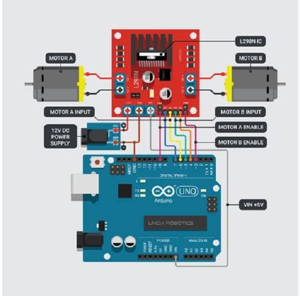 Figure 2: How the L298 H-bridge IC can be connected with Arduino to control two DC motors. Source: Adobe Stock
Components required:
1. BreadBoard
2. Arduino Uno
3. L298N motor driver board module
4. USB cable A to B
5. Jumper wires pack — M/M
6. Jumper wires pack — M/F
The schematic diagram shown in Figure 2 illustrates how L298 H-bridge IC can be connected with Arduino to control two DC motors. Two sets of inputs, one for each motor, are provided to control its direction and the enable pin controls its speed. For Motor A, these are Input1 (IN1), Input2 (IN2) and Enable1 (EN1), whereas for Motor B, these are IN3, IN4 and EN2. The enabled pins must be connected to PWM pins of Arduino so that the motor speed can be controlled according to duty cycle of the PWM. IN1 and IN2 digital values are used to determine which way the motor spins as shown in the table below.
|
L298N Pin States |
Motor State | |
|
IN1 |
IN2 | |
| 0 | 0 | STOP |
| 1 | 0 | Clockwise (Forward) |
| 0 | 1 | Anti-clockwise (Backward) |
| 1 | 1 | Stop |
Example code
The following example code will allow you to first move Motor A in the forward direction and then in the backward direction before it comes to a stop. The code is self-explanatory and can be amended as per the requirements.
const int IN1 = 7;
const int IN2 = 6;
void setup()
{
pinMode(pwm,OUTPUT); //Set PWM pin as output
pinMode(IN1,OUTPUT); //Logic pins are also set as output
pinMode(IN2,OUTPUT);
}
void loop()
{
//For Clock-wise motion, IN1 = High, IN2 = Low
digitalWrite(IN1, HIGH);
digitalWrite(IN2, LOW);
analogWrite(pwm,255); /*PWM of the motor is set to 255 (highest value), it can be changed to change the speed of rotaion
//Clockwise for 2 secs
delay(2000) ;
//For Anti Clock-wise motion — IN1 = LOW, IN2 = HIGH
digitalWrite(IN1, LOW);
digitalWrite(IN2, HIGH);
analogWrite(pwm,155);
delay(2000);
//For stopping the motor
digitalWrite(IN1, HIGH);
digitalWrite(IN2, HIGH);
delay(1000);
}
