Wires are electrical conductors that play an important role in pretty much every industry today by allowing electrical current to travel from one device to another in an electrical circuit.
However, while seemingly simple, there is more to electrical wires than meets the eye. For instance, wires come in different gauge sizes, with each size having its suitability for different application requirements. Besides, engineers must understand several standards and calculations when specifying electrical wires for a particular application.
This article will get back to the basics of wire gauges. It will explain wire gauge sizes using the American Wire Gauge (AWG) standardized system and discuss the suitable applications of different wire gauge sizes.
What is wire gauge and the American Wire Gauge system?
The gauge of a wire simply describes the thickness (or diameter of the wire). Each gauge is represented by a number, with the higher numbers representing thinner wires and the smaller numbers representing thicker wires. Wire gauges allow engineers to determine several specifications of a wire (for example, the wire’s current carrying capacity) and the suitability of specific wires for several applications.
There are several standards used for specifying wire gauges, but the American Wire Gauge (AWG) system is more widely used, especially in the U.S. This standard sets different numbers according to the wire diameter, and it is suitable for specifying sizes for round and solid conductive wires made from non-ferrous metals.
AWG sizes are numbered from 0000 to 40, with the lower-numbered gauge having a larger diameter than the higher-numbered gauge. So, for example, 0 AWG is defined as 0.3249 inches (or 8.25246 mm), and 36 AWG is defined as 0.005 inches (or 0.127 mm) in diameter.
Technical parameters that can be determined using wire gauge sizes
Given the wire gauge size, engineers can determine the following parameters:
1. Diameter
The diameter of an AWG wire can be determined using the following equation:
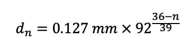
Where:
n = the AWG gauge number, which typically ranges from 0 to 40
So, for example, a 36 AWG wire will have a diameter of
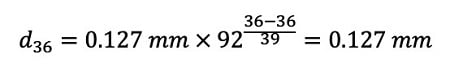
By calculating the wire diameters of different AWG sizes, it can be deduced that the wire diameter doubles for every 6-gauge decrease. For example, the diameter of 30 AWG (0.254 mm) is two times the diameter of 36 AWG (0.127 mm).
2. Area
Since AWG wires have a circular cross-section, the wire gauge area can be obtained using the wire diameter according to the equation:

Where:
d = wire diameter
According to the AWG standard, the cross-section area doubles for every three-gauge decrease. For example, the area of 30 AWG (which is 0.05067 mm2) is approximately two times the diameter of 33 AWG (which is 0.02554 mm2).
3. Resistance
Every electrically conductive wire offers some form of electrical resistance. This resistance (measured in Ohms) depends on the wire length, cross-sectional area, and resistivity, according to the equation below:
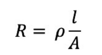
Where:
p = resistivity of the wire
A = wire cross-section area
l = wire length
From the equation, it can be deduced that wire resistance increases as the area reduces. So, given two wires of the same length, the thicker wire (with a lower AWG number) will have lower resistance.
4. Current-carrying capacity
The current carrying capacity describes the amount of electric current that the wire is designed to handle safely. Thicker wires (lower AWG number) have lower resistance. As such, they can carry more electric current than thinner wires (higher AWG number).
Selecting the right wire gauge size using AWG chart
Engineers do not always have to rely on formulas to specify wire gauge size for a particular application. Table 1 presents the standard AWG chart showing gauges from 0000 to 21, including their corresponding diameters and ampacities (maximum electric current that the wire gauge size can safely handle).
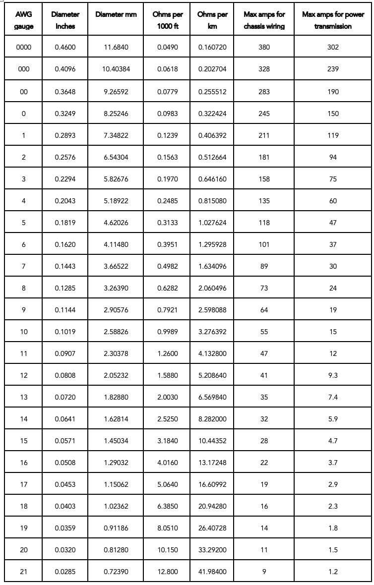 Table 1: AWG chart showing gauges from 0000 to 21
However, before specifying a wire gauge size for a particular electric circuit system, engineers must first calculate the total amperage (or load) of the circuit using:
Where:
P = total load of the system (Watt)
V = supply voltage (Volts)
As a rule, choose a wire gauge size with an amperage rating greater than the circuit's total amperage (or load). Choosing a thinner wire might cause the circuit to melt (or fail) as the heat generated in the wires would be greater than what the wire is designed to handle.
Likewise, engineers must also consider voltage drops in the circuit. This is because there is always some voltage drop when current flows through an electrical wire. It is recommended that the maximum allowable voltage drop across the wire length should be about 2.5% of the supply voltage. In more complex product development, the insulation temperature limit, thermal conductivity and thickness must also be considered.
[Learn more about electric power wires selection on Globalspec.com]
Some suitable applications of different wire gauges
Thin wires (or wires with a high AWG number) are ideal for lighter applications, while thicker wires are suited for heavy-duty applications. Highlighted in Table 2 are some of the common applications of different wire gauge sizes.
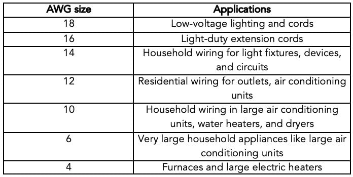 Table 2: Common applications of different wire gauge sizes
While this article presents helpful information about wire gauge sizes, there are still several factors an engineer must consider when specifying wires for a particular electric circuit system. Engineers are advised to reach out to electric power wire manufacturers to discuss their application requirements.
