Sponsored Content
Power
Specifying high-voltage connectors
21 July 2020
Design engineers look for form, fit and function when choosing components for their products. Choosing connectors is no different in general, but when specifying high-voltage connectors for AC, DC or RF applications, function drives the selection. This means choosing connectors suited to the task, preventing the breakdown of insulators and minimizing environmental effects within the connector.
 Figure 1: When specifying high-voltage connectors for AC, DC or RF applications, function drives selection.
While this brief will touch on regulations and standards pertinent to high-voltage applications, it will primarily discuss the atmospheric and environmental effects as well as geometric and material considerations that influence connector choice. With this understanding, design engineers can more easily specify the high-voltage connector that will deliver maximum performance, optimum longevity, long-term reliability and ultimate safety.
IEC (International Electrotechnical Commission) 60038:2009 specifies standard voltage values to be used as references for equipment and system design. However, what constitutes high voltage varies by industry and application. It is important to know the rules, regulations and standards relevant to a product as well as which testing requirements are needed before a product can be released. All of these will be necessary to choose the right connector for an application. In the end, the decision always comes down to analyzing form, fit and function as well as the environment in which the connector will be used.
Function drives high-voltage connector selection
For selecting electrical connectors, it is obvious that one must avoid shock when handling the connectors, that the connector must be made of materials suited to the use and the environment, and that the connector must be durable and not cause a fire. When specifying a high-voltage connector, minimizing the risk of corona and arcing is the key consideration.
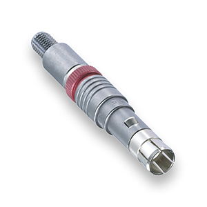 Figure 2: A LEMO 05 series high-voltage connector. Source: LEMO
Corona and arcing
Corona can initiate arcing, which in turn can create fires. Corona results in power loss, thermal breakdown and possible electromagnetic and RF interference. Corona may also cause the breakdown of insulators. The key criteria to minimize corona and arcing are atmospheric and environmental conditions and connector geometries and materials. Atmospheric conditions include temperature, pressure, particulates and humidity. Geometrically, the key considerations are spacing of the conductors to each other and other metal components as well as the effect of sharp corners. Since corona affects porous insulators more than non-porous insulators, this factor should also be considered.
Atmospheric conditions
The relationship of breakdown voltage between two conductors in gas as a function of pressure in gas and gap distance has been discussed extensively beginning with Paschen in 1889. Moongilan included the effects of temperature and humidity on corona inception voltage, showing that lower pressure and higher temperatures produce corona at lower voltages whereas relative humidity itself does not have much of an impact.
However, even in an arid climate, a large change in temperature can result in contaminated condensation, which must be prevented from entering the connector as it reduces the inception voltage for corona discharge.
Geometry and insulation degradation
Given that the distance between conductors influences the inception voltage for corona, the goal is to maximize the distance between conductor pins and other metal parts inside the connector. By understanding a component’s response to partial discharge activity, material selection, geometries and interfaces, connectors can be optimized to increase endurance and reliability.
Dunbar et al. discusses how partial discharge (corona is a type of partial discharge) destroys insulators. Whereas in AC and DC systems breakdown voltage is related more to environmental factors and spacing, in RF systems multipacting breakdown is a function of frequency (MHz) times spacing.
It is best to avoid sharp edges and try to use smooth and rounded surfaces as the former will also reduce inception voltages. Non-porous insulators fair better in general against breakdown but are not always practical inside a small space such as a connector. Incorporating insulating materials such as PEEK, Teflon and silicone rubber in the connector design will maximize creepage distance and air clearance.
In addition to corona, arcing, atmospheric effects, geometry and insulation degradation, other variables must also be considered such as pulsed voltages and voltage surges. High-voltage connector suppliers have already spent the time, energy and research on all these considerations to have their products meet the critical needs of their customers. Discussing all requirements in detail will ensure that the best connector for a particular high-voltage application will be selected.
Learn more about LEMO high-voltage connectors at the LEMO website.
Powered by CR4, the Engineering Community
Discussion – 0 comments
By posting a comment you confirm that you have read and accept our Posting Rules and Terms of Use.
Advertisement
Advertisement
Popular News
Find Free Electronics Datasheets

Advertisement