Sponsored Content
Industrial Electronics
EMC testing ensures compatible electronic products
26 April 2019
Sponsored content
Electronic devices surround us, and the number of devices is growing constantly. From automotive electronic components to cell phones, computers and even life-saving medical equipment, electronic devices, circuits and systems must often work together. For an electronic product in development, electromagnetic-compatibility (EMC) testing simulates the operating environment, with its many electromagnetic (EM) fields. EMC testing is a way to represent the EM environments that a device under test (DUT) or equipment under test (EUT) will face during its lifetime. EMC testing provides the means to understand not only how a DUT will respond when subjected to a level of electromagnetic interference (EMI), but what it will contribute as its own EMI.
EMC measurements are typically performed as EM immunity tests and EM emissions tests. EM immunity testing determines how well an electronic product will perform when exposed to a known level of EM energy. In contrast, EM emissions testing determines how much EM noise a DUT or EUT will radiate and compares those EM levels to an acceptable standard limit.
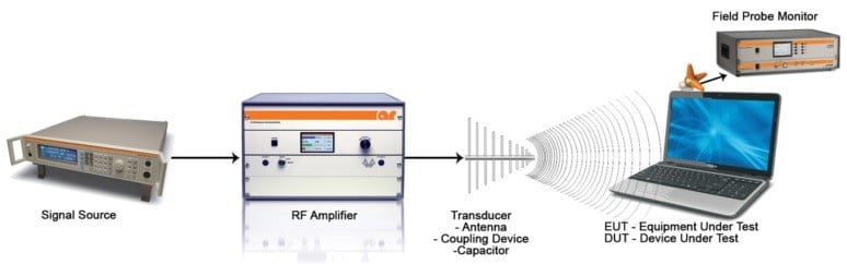 Figure 1. A basic RF radiated immunity test system includes a high-frequency signal generator, power amplifier and antenna, transducer or coupler. Source: AR RF/Microwave Instrumentation
Typically, EMC testing is defined by different standards per industries and their applications, such as the standards developed by the Comité International Spécial des Perturbations Radioélectriques (CISPR) and the International Electrotechnical Commission (IEC). Acceptable EM noise levels are defined by different government organizations, such as the Federal Communications Commission (FCC), and different industry standards, such as standards for aerospace (DO-160G), automotive (International Organization for Standardization (ISO) and Society of Automotive Engineering (SAE) standards), medical (Food and Drug Administration (FDA)) and telecom (European Telecommunications Standards Institute (ETSI) standards) industries, with military users developing their own standards (MIL-STD-461G, MIL-STD-464) and commercial products. Diverse organizations such as the International Electrotechnical Commission (IEC) serve commercial EMC applications with their IEC 61000 family of EMC standards.
Evaluating for EMC
EM energy levels in everyday environments are a concern for the proper operation of electronic devices. The growing number of radio frequency (RF) and microwave signals in the environment can also give rise to interference through conduction, for example, when an interconnecting cable functions as an antenna or when EM is unintentionally coupled onto a cable. For that reason, EMC testing also provides ways to evaluate electronic products for RF conducted immunity — the power levels of RF and microwave signals in the environment that a device can withstand and still operate properly — and RF conducted emissions — the levels of EM interference that an electronic product will generate due to its own use of RF and microwave energy. As with radiated immunity and emissions measurements, RF conducted immunity and emissions measurements are guided by many industry-based standards.
Most standards for the different types of EMC measurements, for emissions or immunity, whether conducted or radiated, also consider the impact of natural effects such as lightning, and man-made effects such as high-power welding machines, on the EM environment and how surges of energy from these sources can affect the performance of an electronic product. Testing to simulate the impact of these effects is usually performed with high-power pulsed test signals. Suitable EMC test equipment must be capable of generating and measuring high-power pulsed energy surges that might result from a lightning strike.
Performing EMC testing
EMC emissions measurements, whether conducted or radiated, depend on detecting small levels (per standards) of EM energy using a sensitive EMI receiver or spectrum analyzer with wide dynamic range. Additional test equipment includes antennas, such as horn and log-periodic antennas, and often a low-noise amplifier (LNA) to boost low-level signals within the dynamic range of the receiver or spectrum analyzer. Since the low-level EM or RF test signals are surrounded by other signals in a normal operating environment, an additional component for most EMC emissions test setup is an anechoic chamber, to isolate the DUT or EUT from unwanted signals during EMC testing.
EMC immunity testing evaluates how a DUT or EUT performs when subjected to known EM and RF energy levels. A basic RF radiated immunity system (Figure 1) employs a high-frequency signal generator, power amplifier and antenna, transducer or coupler to direct EM and RF energy at the DUT or EUT. A field probe is also used to measure test energy levels at the DUT or EUT. As with EMC emissions measurements, radiated immunity testing is often performed within an anechoic chamber to control the test environment.
Radiated immunity testing can be performed as closed-loop measurements or using the substitution method. For closed-loop radiated immunity testing, the radiated field directed at the DUT or EUT is measured and adjusted or leveled during the testing. With the substitution method, a calibrated EM field is directed at the DUT or EUT, with no leveling or adjustments made during the measurements.
Reaching high levels
Power amplifiers play an important role in EMC immunity testing since they boost the RF test signals to the power levels needed to comply with different industry EMC standards and to ensure that a DUT or EUT will perform under real-world EM conditions. An amplifier for EMC immunity testing must be able to reproduce many types of signals, including continuous-wave (CW), amplitude-modulated (AM) and pulse-modulated (PW) signals.
Standard-based EM and RF power and field levels set a starting point when specifying a power amplifier for RF radiated or conducted immunity testing. The amplifier must boost the power levels from a signal generator or other test source while also overcoming losses from cables, connectors, couplers and other components in the test setup. The amplifier must meet specifications for frequency range, output power, linearity, harmonic distortion and load tolerance within a 50 Ω test system impedance to satisfy EMC standards of interest.
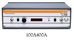 Figure 2. Developed for EMC testing, this amplifier provides 100 W CW output power from 100 kHz to 400 MHz. Source: AR RF/Microwave InstrumentationAs an example, model 100A400A from AR RF/Microwave Instrumentation (Figure 2) is a Class A (highly linear) solid-state amplifier that delivers at least 100 W CW output power from 10 kHz to 400 MHz. With 50 dB minimum gain, it only requires 1 mW input signal power to reach its rated output power level. The 50 Ω, air-cooled amplifier is mismatch tolerant for any load at its rated output power. It features many control interfaces, including USB, RS-232, Ethernet and general-purpose interface bus (GPIB), for ease of connection in automatic test systems. Of course, this is one example of an amplifier for EMC testing, with test requirements for a DUT or EUT setting target levels for an amplifier in any EMC test system.
EMC testing is an important component for new electronics product development. It shows whether the product will function properly with electronic equipment around it and ensures it will not disturb other electronic products. High-power, broadband amplifiers are key components in EMC test systems, if they can meet essential performance parameters.
When a new product is close to its release point, and it is time to perform final EMC testing according to applicable standards, do not forget the amplifier.
Powered by CR4, the Engineering Community
Discussion – 0 comments
By posting a comment you confirm that you have read and accept our Posting Rules and Terms of Use.
Advertisement
Advertisement
Popular News
Find Free Electronics Datasheets

Advertisement