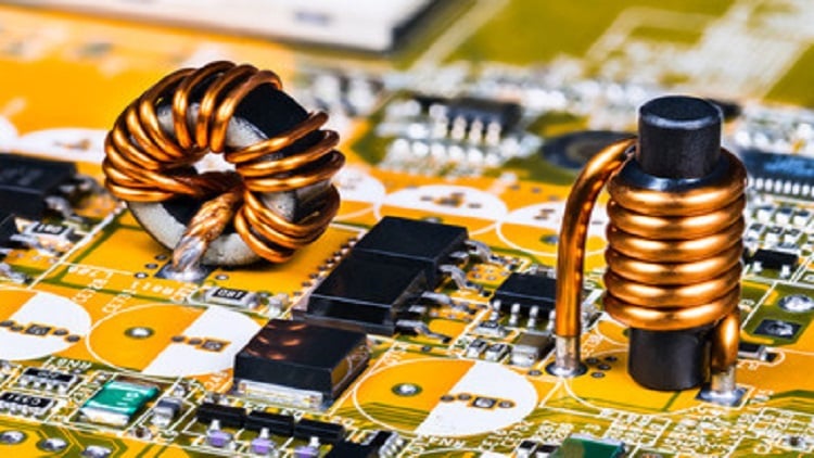
Inductors are among the most commonly used passive electrical components in electrical devices and circuits today. These coil-like structures oppose sudden changes in current and store energy in a magnetic field. This magnetic field is produced when electric current flows through inductors.
However, there is more to inductors than meets the eye. For instance, there are several fundamental concepts and calculations that explain the working of an inductor. In addition, these passive electrical components come in different types, with each type having its suitability for different application needs.
What is the inductance of an inductor?
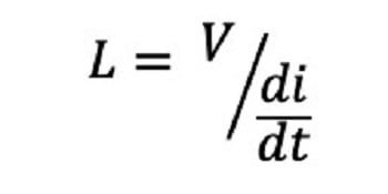
Inductance describes the ability of an inductor to produce electromotive force (EMF) due to a change of electric current flowing through it. It is expressed mathematically as:
Where:
L = inductance (Henry)
V = voltage across the inductor (volts)
di/dt = instantaneous rate of electric current change through the inductor
The inductance of an inductor is a result of the induced magnetic field in the coil. It depends on several factors, including the length of the inductor coil, number of turns and coil diameter.
Learn more about inductors on GlobalSpec.com.
Understanding the working principle of inductors
Before explaining how inductors or coils work, it is essential to first understand how straight conductors behave when electric current flows through them. Therefore, consider a straight conductor, as shown in Figure 1.
 Figure 1: A magnetic field is produced around a conductor when electric current flows through it. Source: stannered/CC SA 3.0
When a steady current passes through such a conductor, a magnetic field is produced around it. The strength of this magnetic field depends on the amount of current flowing through it, while the direction of the magnetic field can be obtained using Fleming’s right-hand rule.
Now, when the current flowing through an inductor is varied, it causes a varying magnetic field to be produced around the inductor coils. This varying magnetic field creates magnetic lines that cut across the coil, inducing EMF opposite in direction to the supply current in the wire. This induced EMF also opposes any change in the supply current, as would be expected according to Lenz’s law.
To better understand how inductors work, consider a simple circuit featuring an inductor connected in parallel to a bulb, as shown in Figure 2.
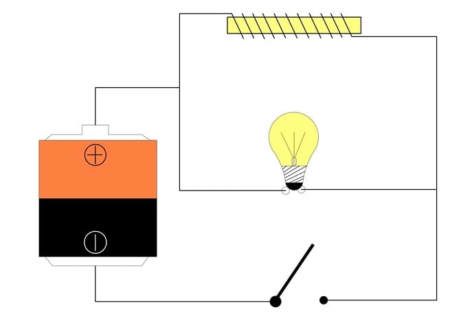 Figure 2: Inductor and bulb circuit. Source: Temitayo Oketola
Given that an inductor (or coiled wire) typically has lower resistance than a bulb, one would expect most of the current to flow through the inductor, causing the bulb to glow dimly. However, this is not exactly what happens. Instead, when the switch is closed, the bulb gets very bright before it gets dimmer. Likewise, when the switch is suddenly opened, the bulb maintains its glow for a while before it goes out.
This behavior is caused by the presence of an inductor. For instance, when the switch is first closed, the inductor gradually builds up a magnetic field, inhibiting current flow. This causes more current to flow through the bulb, causing it to burn very brightly. Once the magnetic field is built, the maximum possible current flows through the inductor coil, causing the bulb to dim.
Likewise, when the switch is suddenly opened, the already-built magnetic field keeps the current flowing normally through the coil until the field collapses. As a result, inductors store energy in their magnetic field and resists change in the amount of current flowing through them.
Inductor circuits: Series and parallel connection
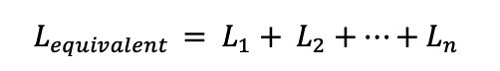
Inductors can be connected in series or parallel. In the series connection, the inductors are connected end to end or chained together in a straight line, as shown in Figure 3.
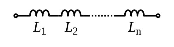 Figure 3: Inductors in series. Source: Omegatron/CC SA 3.0
The equivalent inductance of such an inductor circuit is a sum of all the individual inductances. However, the current flowing through each inductor is the same, while the voltage differs according to the inductance value of the inductor.
In parallel circuit configuration, the two terminals of an inductor are connected to the two terminals of one (or more) inductors.
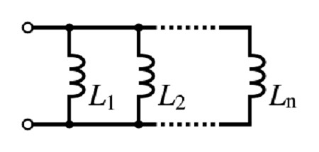 Figure 4: Inductors in parallel. Source: Omegatron/CC SA 3.0
The equivalent inductance of this circuit can be obtained using:
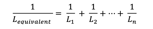
As the equation above shows, the equivalent inductance decreases. However, unlike the series configuration, the current flowing through each inductor differs while the voltage across each of the inductors in parallel remains the same.
Choosing an inductor for an application
Inductors come in several types: air-core, toroidal core, ferrite core and ceramic core inductors, among others. The ideal choice will depend on the application requirement. For instance, air-core inductors are commonly used for radio frequency applications because of their low losses at high operating frequencies. However, they are not ideal in applications where they will experience vibration as it affects their inductance.
Therefore, engineers are advised to reach out to inductor and coil manufacturers to discuss their application needs.
