Sponsored Content
Aerospace
Space-rated active optical cable: Mission-critical reliability through extensive analyses and rigorous testing
25 July 2019
Sponsored content
Increasing data requirements on spacecraft are driving the need for high-speed, on-board networks. The trend is fueled by technology improvements in avionics modules and payload instruments such as advanced optical sensors that generate high-resolution data. Prior to transmitting information back to Earth with high-gain antennas via an RF communications downlink, large volumes of data are sent over the local network from instruments to on-board storage used as a buffer.
A critical component of these satellite networks is the high-bandwidth cable carrying data signals between modules. As data rates rise, there is a need for reliable, high-speed cable solutions that outperform traditional links like serial copper coaxial cable. As a result, spacecraft designers are exploring alternatives like high-speed fiber optic transmission cables. A subset of these is known as active optical cables (AOC).
What is an AOC?
Unlike conventional fiber optic cables, which consist of optical fibers terminated by optical connectors, an AOC is an optical fiber with electrical connectors at each end. Inside of the electrical connectors are optical transceivers that convert electrical signals to optical signals and vice versa. An AOC receives electrical signals over an electrical interface, converts those signals to optical signals, transmits the optical signals over an optical fiber, reconverts the optical signals to electrical signals and outputs the electrical signals over another electrical interface.
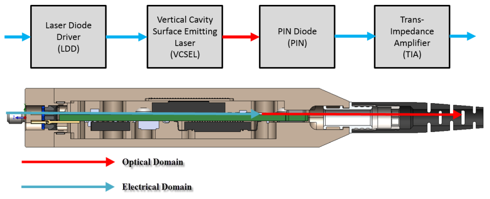 Figure 1: AOC connectors contain transceivers with optical engines that convert electrical signals to optical signals and vice versa. Source: AirBornThe optical transceiver circuit in the electrical connector of an AOC is the optical engine that performs the electrical-optical conversion. A laser diode driver drives a vertical-cavity surface-emitting laser (VCSEL) to convert electrical signals to light, which is then coupled to the optical fiber. At the other end of the AOC, a photodiode connected to a trans-impedance amplifier — typically consisting of a trans-impedance pre-amplifier, a limiting amplifier and a current mode logic output stage — converts the optical signals back to an electrical signal.
Widely used in commercial applications, most commonly in data centers for high-bandwidth data transmission, AOC technology has matured, and now AirBorn Inc. has developed a ruggedized version for use onboard spacecraft. AirBorn’s space-rated active optical cable (SAOC®) assembly is engineered to withstand the harsh conditions of space and replaces traditional copper or fiber optic cable assemblies on spacecraft. The SAOC® assembly is the result of a four year-long engineering effort backed by rigorous analysis and testing. The product comes from a company trusted for over 60 years as a designer and manufacturer of specialized connectors and electronic components engineered to provide mission-critical reliability in extreme conditions for aerospace, defense, industrial and other applications.
Benefits of AOCs
AOCs provide many benefits that fiber optic cable assemblies offer in comparison to copper cable assemblies, while delivering the ease-of-use of a copper electrical interface.
AOCs transmit data at high rates (AirBorn’s SAOC® assembly supports speeds up to 14 Gbps per lane) without signal degradation over longer distances than copper. AOCs also weigh less than copper. This lowers total mass to make spacecraft more maneuverable and reduces the fuel burned to reach orbit, resulting in lower launch costs. Alternatively, capacity is freed up for other payloads such as high-value science instruments.
AOCs offer smaller cable diameters than copper, facilitating installation and routing in space-constrained satellites and spacecraft. In addition, AirBorn’s SAOC® assembly transceivers are carefully sealed against radio-frequency interference (RFI). Moreover, optical fibers are immune to RFI from adjacent cables and do not produce RFI themselves, so no additional RF shielding is needed around the fiber. The nonmetallic fiber-optic structure also provides inherent electrical isolation that minimizes the potential for ground loops.
In addition to their advantages over conventional copper coaxial cables, AOCs are in many ways superior to traditional fiber optic cables. Compared to fiber optic connectors, the copper interfaces at the ends of AOCs have multiple points of contact to better withstand shock and vibration, more robust housings and higher overall ruggedness. AOCs are also easier to install and maintain. Fiber optic optical interfaces are susceptible to contamination, requiring routine inspection and cleaning. The electrical interfaces of AOCs eliminate these tasks by sealing vulnerable optical components inside the assembly.
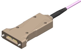 Figure 2: Space-rated MicroSI high-speed Micro-D SAOC®. Source: AirBornAirBorn’s SAOC® assembly offers design flexibility. Since the connector interface at the end of an SAOC® assembly is the same as the connector interface at the end of a copper cable, a single box design can accept both SAOC® and copper assemblies. This makes it easy to use copper cable and SAOC® assemblies interchangeably, deploying copper for short runs and SAOCs® for longer runs. Furthermore, since electrical/optical conversion is accomplished by the SAOC® assembly, there is no need for transceivers on the PCBs of the receiving or transmitting avionics, simplifying box design.
SAOC® assemblies accommodate multiple interfaces for data, power, telemetry and command. The product’s high-speed data interface provides a full-duplex, high-speed data path, while its power interface enables the host to provide power to the SAOC® assembly. 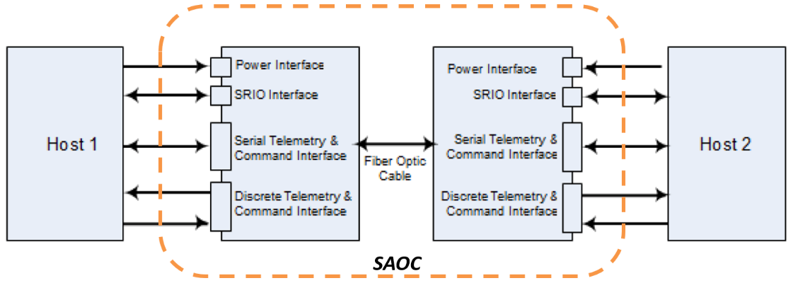 Figure 3: Functional overview of an SAOC® assembly illustrating its power, data, telemetry and command interfaces. Source: AirBornA serial telemetry interface provides serial telemetry over a two wire interface (TWI) bus and a separate discrete telemetry and command interface allows the host to detect and command the SAOC® assembly.
AirBorn’s SAOC® technology can also be adapted to a wide range of connector form factors, including Micro-D, Nano-D, verSI, 38999 and Series 360. Hybrid SAOC® assemblies are possible with a different connector form factor at each end of the cable, for example verSI to 38999. The potential for a variety of assembly options also exists, including SAOC® to passive fiber and SAOC® assemblies with the capability to transmit power and optical signals in the same assembly.
What sets AirBorn’s SAOC® assemblies apart from commercial AOCs?
Typical commercial AOC assemblies are designed to operate in Earth’s relatively benign atmospheric conditions. They are built with non-ruggedized components and lack extensive performance validation. Exposed to the conditions a spacecraft encounters, standard commercial AOCs are vulnerable to failure.
In contrast, AirBorn’s SAOC® assemblies are comprised of robust hardware engineered to withstand the harsh environment of space and are subjected to rigorous, comprehensive testing, analysis and screening to verify performance. The SAOC® assemblies’ radiation-hardened components stand up to harsh radiation, wide operating temperature ranges enable operation in extreme temperatures and robust design tolerates exposure to vacuum. In addition, AirBorn’s SAOC® assemblies meet outgassing requirements, minimizing the release of gas from the cables and components in the vacuum of space.
To ensure high reliability, AirBorn’s SAOC® assemblies have been evaluated through detailed design analyses and rigorously tested to demonstrate technical performance over qualification levels for shock, vibration, temperature, vacuum and radiation. Of the components that comprise AirBorn’s SAOC® assemblies, 100% are screened to guarantee proper operation. Moreover, a built-in health check monitoring system allows optical performance monitoring in real-time in the field.
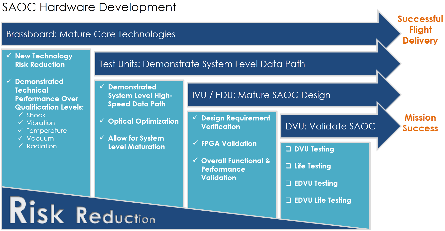 Figure 4: AirBorn's SAOC® hardware development process consisted of extensive analysis and testing to reduce risk and maximize reliability. Source: AirBorn
AirBorn’s tough AOC technology is not limited to space applications. The company has the capability to create non-space, ruggedized versions of the same solution — rugged active optical cable (RAOC®) assemblies — for military or industrial applications such as head-mounted displays and communications systems.
Space qualification analyses
Throughout SAOC® hardware development, AirBorn performed extensive design analyses to provide confidence in SAOC® design maturity and to ensure functionality in harsh space environments.
Comprehensive design analyses were completed to guarantee that AirBorn’s SAOC® assemblies would meet mission requirements. A radiation vulnerability assessment ensured that the product can withstand the expected radiation exposure. The assessment included a review of the mechanical shielding, the unit’s ability to withstand the total ionizing dose (TID) and evaluation of radiation induced attenuation (RIA), a darkening of optical materials such as the fiber caused by exposure to radiation.
Failure modes, effects and criticality analysis was performed to ensure a thorough understanding of the design of SAOC® assemblies and to assess single-point failures and their impact on the spacecraft. Worst-case analysis (WCA) was also carried out to ensure the product’s design would meet requirements with a high level of confidence. The WCA evaluated part of the electrical stress, the telemetry and command interface, decoupling, de-rating, timing, logic compatibility, link margin, power sequencing, power consumption and signal integrity.
A complete design package was developed for the SAOC® assemblies including mechanical drawings and models, electrical drawings and models, drawing tree, bill of materials and electrical, electronic, electro-mechanical and electro-optical parts list.
An end-to-end contamination control plan was created to limit the introduction of contamination into the product along the entire manufacturing pipeline, from component procurement through customer receipt. In addition, a hybrid qualification plan was devised to completely qualify procurement of the unit’s hybrid elements, die attach and wirebonding.
An independent verification and validation of the design of the field-programmable gate arrays in the transceivers inside of the cable assembly’s connectors was completed to ensure adherence to requirements.
Stress and dynamics analyses were performed to ensure the SAOC® assembly has design margin against the complete spectrum of dynamic and thermal environments it will encounter in the field. These included thermal transfer analysis evaluating the transfer of heat in the product, thermal stress and fatigue analysis assessing the effects of heat on solder, epoxies and other materials in the product, and power spectral density analysis to characterize the dynamic response of the product to random vibrational loads.
Other analyses completed include venting analysis to ensure the SAOC® assembly tolerates depressurization and pressurization cycles, mass properties analysis of all component masses and the center of gravity and electrical and RF simulations and models for complete S-parameter analysis.
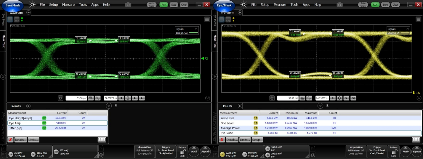 Figure 5: Electrical and optical data eyes were evaluated over -34° C to 95° C in 5° C increments. iMod and iBias were optimized for ambient conditions and temperature extremes. Source: AirBorn
Space qualification testing
AirBorn demonstrated the SAOC® assembly’s design maturity and verified its technical performance and ability to meet design requirements through a comprehensive suite of tests.
Radiation testing exposed the product’s electrical components to radiation to evaluate displacement damage dose, single event effects and TID effects. Optical materials were screened for TID attenuation levels.
Electromagnetic compatibility and electromagnetic interference (EMI) tests measured the SAOC® product for electromagnetic emissions while connected to a host device, verifying that no emissions were observed above the noise floor of the host.
Thermal cycling and thermal vacuum testing evaluated the SAOC® assembly’s full functionality while in a thermal vacuum chamber cycling from -34° C to 95° C at standard pressure and in a vacuum of less than 1E-7 torr. Thermal life tests assessed the SAOC® assembly’s full functionality while in a thermal vacuum chamber cycling from -34° C to 95° C until the product reached over two times the expected thermal fatigue damage predicted over the mission.
Random vibration tests qualified units by exposing them to accelerations in excess of 80 Grms for up to 30 minutes, greater than 10 times mission duration requirements. In addition, performance testing verified the SAOC® assembly compliance to electrical requirements including power, serial telemetry, discrete telemetry and high-speed bit error rate testing. Furthermore, data eye testing validated units’ ability to meet data eye mask requirements across the temperature range.
VCSEL and PIN life testing was performed independently by AirBorn to test the reliability of the VCSEL and PIN photodiode across multiple temperatures and bias conditions. Temperature and humidity testing validated SAOC® and component performance at 85% RH and 85° C.
Applications
With this proven testing and analysis, AirBorn’s SAOC® and RAOC® assemblies are ideally suited for a broad range of applications, both in space and in harsh, non-space environments. Figure 6 lists a number of conditions where SAOC® or RAOC® assemblies may be a better alternative than either traditional fiber or copper cable assemblies.
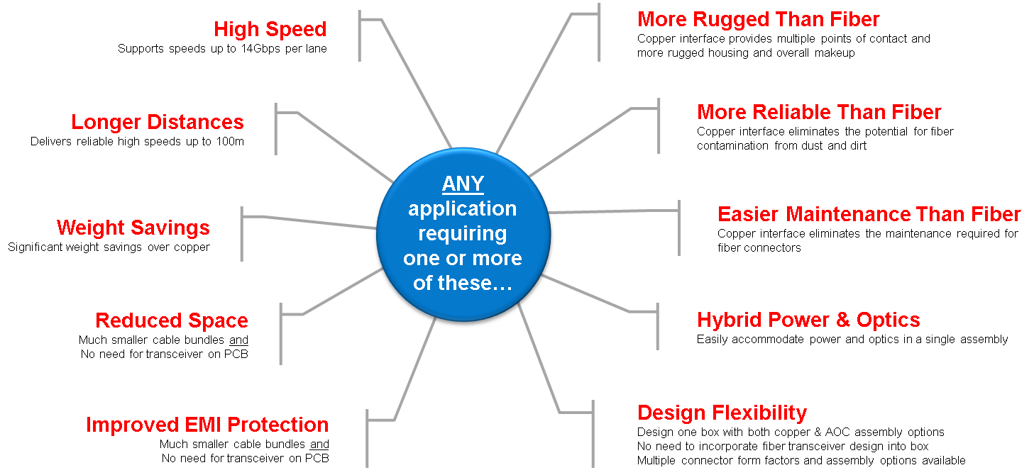 Figure 6: AirBorn’s SAOC® and RAOC® assemblies are ideally suited for a broad range of applications in which any number of these requirements need to be addressed. Source: AirBorn
Conclusion
AirBorn’s SAOC® and RAOC® technology delivers the benefits of fiber optics with the ease-of-use of copper electrical interfaces. Rugged, compact packages support high data rates over long distances with no EMI concerns. Design flexibility is enabled by a wide range of connector form factors, a variety of assembly options and simplified box designs that can accept SAOC® and copper assemblies interchangeably.
AirBorn’s development process for their SAOC® assemblies focused relentlessly on a rugged design engineered to withstand the harsh environments of space. The process consisted of comprehensive analyses and an extensive, rigorous testing regime to validate technical performance over shock, vibration, temperature, vacuum and radiation qualification levels. The cables are built with robust hardware and 100% of the components are screened to guarantee reliability.
Contact AirBorn today to request more information about their SAOC® and RAOC® assembly offerings and learn how these rugged cable assemblies can serve as the optimal solution to meet the needs of aerospace, military or industrial applications.
Powered by CR4, the Engineering Community
Discussion – 0 comments
By posting a comment you confirm that you have read and accept our Posting Rules and Terms of Use.
Advertisement
Advertisement
Popular News
Find Free Electronics Datasheets

Advertisement