Sponsored Content
Industrial & Medical Technology
Addressing Phase Noise Challenges in Radar and Communication Systems
16 January 2018
Sponsored content
![]() Phase noise is rapidly becoming the most critical factor addressed in sophisticated radar and communication systems. This is because it is the key parameter defining target acquisition in radars and spectral integrity in communication systems. There are many papers detailing the mathematical derivation of phase noise but few mention the reasons for its importance. In this Tech Brief, we discuss the importance of phase noise, and what can be done to lessen its effects in microwave systems.
Phase noise is rapidly becoming the most critical factor addressed in sophisticated radar and communication systems. This is because it is the key parameter defining target acquisition in radars and spectral integrity in communication systems. There are many papers detailing the mathematical derivation of phase noise but few mention the reasons for its importance. In this Tech Brief, we discuss the importance of phase noise, and what can be done to lessen its effects in microwave systems.
What is Phase Noise?
Phase noise is commonly used as a measure of frequency stability within an oscillator. This noise is inherently different than the general background noise of any electrical system, which is defined as kTB, where k is Boltzmann’s constant, B is the bandwidth, and T is the temperature. Instead, phase noise is a secondary effect directly related to the topology and construction of the oscillator. A pictorial representation of phase noise is given below in Figure 1.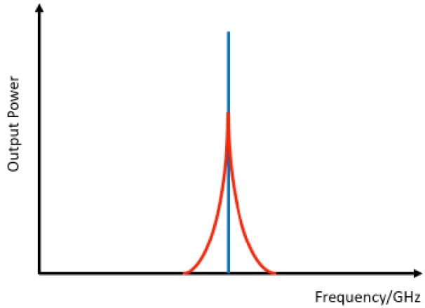 Figure 1. Pictorial representation of an ideal signal (blue) and a signal with phase noise (red).
In this figure, we have plotted the output power of an oscillator versus frequency. The ideal oscillator is shown in blue, which only outputs power at a single, fixed frequency. The red curve, however, is the output of an oscillator with phase noise, which shows up as power across a spectrum of frequencies very close to the desired output. These skirts, as they are called, are always present and are due to thermal noise within the active devices of the oscillator. The power level of the red skirts is dependent upon the quality of the oscillator and is measured in dBc/Hz at an offset frequency from the desired signal (typically called the carrier).
Why do we care about Phase Noise?
Phase noise can affect the performance of many different microwave systems. In this Tech Brief, we
discuss two in particular: direct down conversion receivers, and radars.
Direct downconversion is a type of receiver in microwave communication systems. One benefit of direct downconversion is the simplicity of the circuit, which is essentially a single mixer driven by a local oscillator (LO) to convert the input RF signal to a baseband (very low frequency). This baseband signal is then directly applied to an analog-to-digital converter for processing. A common term for this architecture is “RF in, bits out”. One problem with direct downconversion, though, is that the input RF signal can be very close in frequency to the LO, which makes the conversion process susceptible to phase noise, especially if the signal strength is low.
In radar systems, the problem is similar in nature.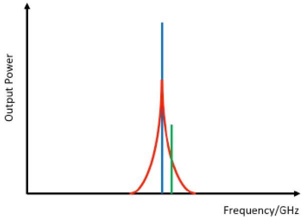 Figure 2. Pictorial representation of an ideal LO signal (blue), an LO signal with phase noise (red), and an RF signal close in frequency (green) we wish to convert to baseband. Radar systems operate by transmitting a pulse at one frequency, and then measuring the frequency shift of the returned pulse, as the shift is related to the velocity of the object being imaged through the Doppler effect. Objects moving very slowly will generate a return pulse very close in frequency to the transmitted pulse, and if the cross section of the object is also very small, the power level of this received signal will be also very low. Ultimately this return pulse has to be converted to baseband in order to recover the velocity information, and phase noise can obscure the data.
A pictorial representation of the dilemma faced by direct conversion receivers and radar systems is shown in Figure 2. In this figure, we can see that if the power level of the RF signal we wish to convert falls below the phase noise spectrum of the LO signal, we will be unable to recover any baseband information, as the signal will be in the noise. Therefore, reducing the phase noise will increase our receiver sensitivity.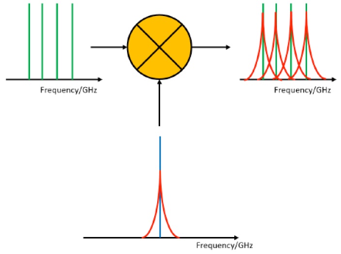 Figure 3. Pictorial representation of phase noise issues in OFDM systems. Ideal LO signal (blue), LO signal with phase noise (red), RF signal (green).
In Figure 3, we present a second pictorial example of how phase noise can negatively impact a conversion, this time of a multi-carrier orthogonal frequency-division multiplexed (OFDM) signal.
In this figure, we note that if the phase noise of the LO is too high, then the noise will be converted into adjacent channels of the baseband data, thereby ruining the integrity of the information.
Amplifiers and Phase Noise
One obvious place to limit phase noise is in the choice of oscillator. This problem can be addressed by spending considerable time and money to design or procure a low noise oscillator. However, most oscillators do not generate enough output power, and indeed let us assume that for a particular application, the oscillator output of +5 dBm needs to be amplified to a level of +15 to +17 dBm, in order to drive the LO
port of a mixer. The question then becomes, does the amplifier affect the phase noise of the LO signal?
In an ideal situation,  Figure 4. CMD167 LNA Phase Noisethe answer would be “no,” as the amplifier would simply raise desired LO signal and the skirts by the same level. However, in reality, microwave amplifiers add noise of their own to any signal, and herein lies the problem. All electronic devices exhibit a phenomenon called 1/f noise or “pink noise”, which is noise power that is added to an input signal spectrum but falls off proportionally to the inverse of the offset frequency. In Figure 4, we present the phase noise of the CMD167, a low noise amplifier covering the 10 to 17 GHz range, versus offset frequency away from the desired signal. The phase noise of the incoming signal has been canceled out, so this plot represents the noise generated by the amplifier.
In Figure 4, we note the phase noise falls off linearly on the logarithmic scale with increasing frequency offset, which is characteristic of 1/f noise. If this noise level is higher than the phase noise of the input signal, then the amplifier noise would dominate the output noise spectrum. In our example, this means the low phase noise of the oscillator would be replaced by the higher phase noise of the amplifier, thereby defeating the purpose of the low phase noise oscillator. A pictorial representation of this phenomenon is shown in Figure 5.
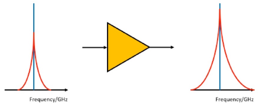 Figure 5. Pictorial representation of the degradation of phase noise due to an amplifier. The skirts of the input signal on the left are increased after passing through the amplifier, with the output spectrum on the right.
One obvious question is, can anything be done to lower the phase noise of amplifiers? The answer lies in device physics. The 1/f noise is caused by random and thermal charge movement in the channel of an active device. The CMD167, for example, is manufactured on a Gallium Arsenide (GaAs) pHEMT process with a gate length of 0.13 um. The FET devices on this process typically have a high 1/f corner due to their high electron mobility. GaAs bipolar devices, on the other hand, tend to have lower electron mobilities, which means a much lower 1/f noise, so they are considerably better for phase noise than their FET counterparts. Therefore, one solution to lowering the additive phase noise is to use a GaAs HBT process.
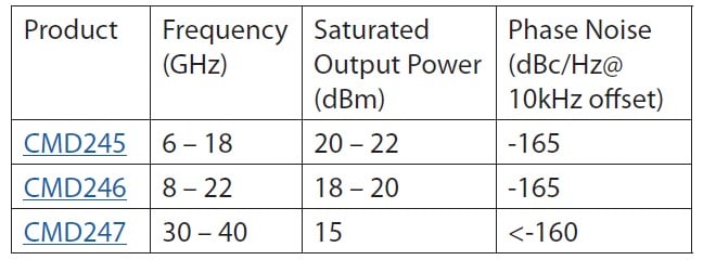 Table 1. Summary of Custom MMIC’s new Low Phase Noise Amplifiers (LPNAs) die. SMT packaged versions are also available.At Custom MMIC we have used our extensive knowledge of amplifier design techniques to create a family of new Low Phase Noise Amplifiers (LPNAs) on a GaAs HBT process operating from 6 to 40 GHz. In Table 1, we present the summary characteristics of these new amplifiers.
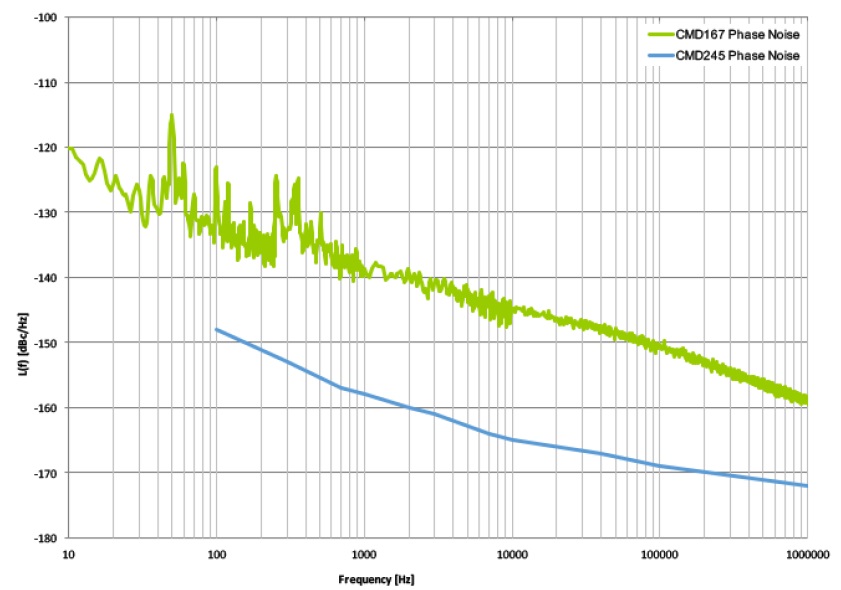 Figure 6. Phase noise of the CMD245C4 low phase noise amplifier vs CMD167 LNA.In Figure 6, we present the phase noise versus offset frequency for the CMD245 amplifier as housed in a 4 mm QFN-style package, relative to the CMD167 HEMT LNA shown previously. We note the phase noise of the CMD245C4 is 15 to 20 dB lower than the CMD167 pHEMT LNA.
Other Components and Phase Noise
Other components besides oscillators and amplifiers can contribute to phase noise, including frequency multipliers. Many microwave systems utilize a lower frequency oscillator that is then multiplied to produce a higher frequency. One common approach for multiplication is to use a harmonically terminated amplifier to generate the required output frequency. Unfortunately, such an approach will then add the amplifier’s phase noise to the multiplied signal, which will degrade the phase noise of the original oscillator.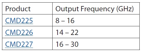 Table 2. Summary of Custom MMIC’s passive multiplier die family. SMT packaged versions are also available.
A second approach is to use passive multiplication, which has the potential to add minimal additional phase noise to the multipliers signal (aka doublers). Custom MMIC, has also created a family of passive HBT style frequency multipliers which do not add to the phase noise of the input signal. In Table 2, we present a summary of these multipliers.
Powered by CR4, the Engineering Community
Discussion – 0 comments
By posting a comment you confirm that you have read and accept our Posting Rules and Terms of Use.
Advertisement
Advertisement
Popular News
Find Free Electronics Datasheets

Advertisement