Electric vehicle (EV) charging connectors are the critical interface between the charging station and the vehicle. They must safely deliver significant electrical power under varying conditions, all while enduring thousands of plug-in cycles and harsh environments. This article explores how modern EV charging connector designs handle both AC charging (which uses the vehicle’s onboard charger) and DC fast charging (directly feeding the battery), focusing on the major connector standards — CCS, CHAdeMO and Tesla’s NACS — and the engineering features that ensure electrical safety and long-term durability.
AC charging connectors
AC charging connectors (Level 1 and Level 2) supply alternating current to an EV’s onboard charger. They typically deliver up to ~7 kW to 22 kW (depending on single-phase or three-phase supply) and use relatively smaller pins and cables since the onboard charger limits current (e.g., 16 A to 80 A). Common AC connector types include the SAE J1772 Type 1 (used in North America/Japan) and the Type 2 “Mennekes” (used in Europe). Type 1 has five pins and supports single-phase up to 19.2 kW (80 A at 240 V), while Type 2 has seven pins and can support three-phase AC up to 22 kW. Both use standardized control signaling to communicate with the vehicle. Notably, Type 2 inlets feature an automatic locking pin on the vehicle side to secure the plug during charging, whereas Type 1 plugs rely on a manual latch.
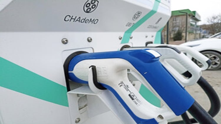
DC charging connectors
DC fast charging connectors (Level 3) deliver high-voltage DC directly to the battery, bypassing the onboard charger. They handle much higher power — today’s systems range from 50 kW to 500 kW at public stations. To accommodate this, DC connectors have larger diameter power pins and thicker, sometimes liquid-cooled, cables. For example, the CCS (Combined Charging System) connectors can carry up to 500 A and 1,000 V (up to ~360 kW) in their latest iterations. Industry high-power charging (HPC) implementations even approach 500 kW continuous (and short bursts to ~700 kW) using advanced cooling and cabling. Tesla’s NACS (North American Charging Standard) connector, newly adopted by many automakers, is surprisingly compact yet supports both AC and DC: it has been tested up to 1,000 V and 900 A (with the system dynamically limiting current to keep connector temperature ≤105° C). This corresponds to potential power levels in the high hundreds of kW, well beyond the 250 kW that today’s Tesla Superchargers typically deliver.
Electrical safety features in connector design
EV charging connectors are engineered with multiple layers of safety to prevent electric shock, arcing or equipment damage. They are designed to have:
• Robust insulation and enclosures: All connector handles and plugs are made of high-strength, flame-retardant insulating materials that prevent the user from touching live contacts. The contact pins are typically recessed and shrouded in insulating plastic so that they are finger safe. Many connectors include shielding or insulating barriers to eliminate exposed conductors, even if the exterior casing is damaged. Connectors are also built to meet stringent safety standards (such as UL 2251 and IEC 62196), requiring them to pass tests for dielectric withstand, insulation resistance and flame resistance (UL94 V-0).
• Grounding and pin sequence: EV connectors are designed so that the ground pin establishes contact first and breaks last. This ensures any stray currents have a return path and that the vehicle chassis is grounded before power flows. Additionally, proximity and pilot signal pins engage early to manage the charging handshake (see below) before high-voltage pins are energized. The result is that no high voltage is present on the main power pins until the plug is fully inserted and the control system confirms it’s safe. This sequencing prevents users from encountering live contacts and minimizes arcing during connect/disconnect.
• Control pilot and communication protocols: Modern connectors carry low-voltage signaling lines that orchestrate the charging process. In AC charging (Type 1/2, CCS, NACS), a control pilot (CP) line per the IEC 61851 standard is used to detect the vehicle, negotiate available current and only then permit charging to commence. A proximity pilot (PP) or similar circuit detects when the plug is latched and can tell the vehicle that a connector is present (often also disabling the vehicle’s drive system during charging). In DC fast charge (CCS), once the analog handshake is done, a digital communication (PLC based on ISO 15118/DIN 70121) takes over on the CP line to exchange battery voltage, desired current and state of charge before high voltage is applied.
• Interlocks and locking mechanisms: To prevent accidental unplugging under load (which could cause arcing), connectors incorporate mechanical or electro-mechanical locks. CCS connectors feature an actuator lock — on CCS Type 2, a lock pin in the vehicle inlet secures the plug in place during charging, while CCS1 plugs have a latch that clicks into the car’s inlet, often sensed by a microswitch. Tesla’s NACS relies on an electronic latch in the vehicle that grabs the connector; a button on the NACS plug sends a signal (via wireless or pilot line) to command the car to release the latch when charging is done. Additionally, connectors and inlets have microswitches or sensors that act as interlocks: the charging station won’t energize if the connector is not securely latched, and if the latch/button is pressed the station will shut off power immediately before the plug is withdrawn. This interlock design ensures the coupler cannot be disconnected under load, and no live power is present on pins when disconnected.
• Thermal monitoring and protection: High charging currents can generate substantial heat at the connector pins. Thus, many DC charging connectors integrate temperature sensors (e.g. thermistors or RTDs) within the connector or inlet to monitor heat buildup. If a plug or coupler starts to overheat — whether from a fault, high ambient temperature or extended fast charge session — the charging system will either shut down or throttle the current to avoid damage or fire.
Conclusion
EV charging connectors combine electrical high-power transfer with robust safety systems and rugged durability. Standards like CCS and NACS encapsulate a decade of learning in EV infrastructure — resulting in connectors that can handle hundreds of kilowatts, auto-detect faults and endure thousands of uses in all weather. As EV adoption accelerates, these connector designs continue to be refined (e.g., upcoming Megawatt Charging System for trucks) but the core principles remain: deliver power efficiently, keep users safe and last long enough to make charging convenient and reliable for all.
